Additional Chapters
4-bit binary counter
Warning
This example is somewhat advanced, and you should not worry if you are unable to follow all the details. They will become clear as the course progresses.
In order to demonstrate how the digital output really works we are goint to create a 4-bit binary counter. First we will use the Arduino function to access the digital outputs, and afterwards we will access the output register directly, in order to demonstrate how this can optimize our program.
Start by building the following circuit. In order to comply with the upcoming example code, you should use the same digital output pins, as shown in the figure.
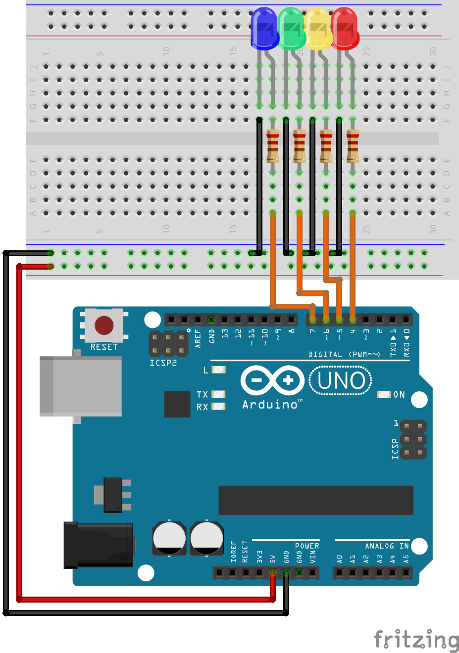
The following program counts the LED’s in the binary sequence from 0 to 15. Each call to digitalWrite only updates one output, and thus we use several conditional sentences to make sure the functions are invoked at the correct time. In addition the program prints the status of the counter to the serial port.
#include <Arduino.h>

void setup() {
  // put your setup code here, to run once:
  pinMode(4,OUTPUT);
  pinMode(5,OUTPUT);
  pinMode(6,OUTPUT);
  pinMode(7,OUTPUT);

  Serial.begin(9600);

}

void loop() {
  // put your main code here, to run repeatedly:

  for(int i = 0; i < 16; i++){

    Serial.write("Tallet er: ");
    Serial.print(i);
    Serial.write('\n');

    if(i%2)
      digitalWrite(4,HIGH);
    else
      digitalWrite(4,LOW);


    if((i/2)%2)
      digitalWrite(5,HIGH);
    else
      digitalWrite(5,LOW);


    if((i/4)%2)
      digitalWrite(6,HIGH);
    else
      digitalWrite(6,LOW);


    if((i/8)%2)
      digitalWrite(7,HIGH);
    else
      digitalWrite(7,LOW);

    delay(1000);
  }

}
Computers work with binary numbers, and thus one might be suprised about the complexity of the code involved just to make the computer count from 0 to 15, and indeed there is a simpler solution.
The problem arrises from the digitalWrite function, restricting our access to only one output at a time. Internally though, at a lower level, the outputs are contained in 8-bit registers, and a single CPU instruction is capable of modifying 8 outputs. If we can figure out which register to modify, we could simply increment the value of this register by one, from 0 to 15 to achieve the same result. Direct register access will make your code less portable and readable, and thus it should be used with causion.
Note
A experienced programmer would typically write some kind of wrapper to isolate as much as possible of the logical code, from the code that directly interacts with hardware. That way only the direct hardware access code must be changed if porting to a different microcontroller.
By looking at the Arduino UNO pinout, we see that the pins we happen to be using (pin 4 - 7) are connected to port PD4 to PD7 in the microcontroller. The following code configures these pins as outputs, and sets PD7, and PD5 high, illuminating the two LED’s.
#include <Arduino.h>

void setup() {
  // put your setup code here, to run once:

  DDRD = 0b11110000; // Configure PD4 - PD7 as outputs, the rest as inputs.
}

void loop() {
  // put your main code here, to run repeatedly:

  PORTD = 0b10100000;
}
The counter may be implemented by incrementing the 4 most significant bits of the PORTD register from 0 to 15. This is achieved by shifthing the value in the counter variable i 4 places to the left using the bit-shift operator <<.
#include <Arduino.h>

void setup() {
  // put your setup code here, to run once:

  DDRD = 0b11110000; // Configure PD4 - PD7 as outputs, the rest as inputs.
}

void loop() {
  // put your main code here, to run repeatedly:

  for(int i = 0; i < 16; i++){
    PORTD =  (i << 4);
    delay(1000);
  }
}
Note
As a simple exercise you could try to extend the program to a 8-bit counter. In that case you might want to reduce the time delay.
Creating a counter with more than 8 bit introduce an additional challenge because you have to manipulate more than one output register. It is however rather straightforward once you know how to do bitwise manipulations.
Using a potentiometer to test the analog to digital converter
Warning
This is a rather complex example, and is mostly intended as a demonstration. It is not expected that you will be able to follow all the details of the code this early in the course.
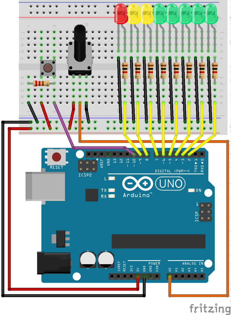
In this example we will be using a potentiometer to apply a varying voltage to the ADC of the Arduino. The conversion result will be fed back to us using the serial UART. In addition a bar of 8 LED’s will be used to indicate the voltage level. The software supports two modes for the LED display, a dot-mode, and a bar-mode.
Warning
This code could (should?) be improved.
#include <Arduino.h>

enum State_enum {BAR_STATE, DOT_STATE};

void led_bar(int);
void led_dot(int);
int buttonPressed(uint8_t);


void setup() {
  // put your setup code here, to run once:

  pinMode(2,OUTPUT);
  pinMode(3,OUTPUT);
  pinMode(4,OUTPUT);
  pinMode(5,OUTPUT);
  pinMode(6,OUTPUT);
  pinMode(7,OUTPUT);
  pinMode(8,OUTPUT);
  pinMode(9,OUTPUT);

  pinMode(10,INPUT);

  Serial.begin(9600);

}


void loop() {

  // put your main code here, to run repeatedly:
  int adc_reading = 0;
  float voltage = 0;

  unsigned long past = 0;
  uint8_t state = BAR_STATE;

  for(;;){

    delay(100);
    adc_reading = analogRead(0);
    voltage = adc_reading*0.00489;


    /*
     * Only write to the serial port once every second.
     */
    if((millis() - past) > 1000){
      past = millis();

      Serial.print("ADC verdi: ");
      Serial.print(adc_reading);
      Serial.print('\n');
      Serial.print("Spenning: ");
      Serial.print(voltage);
      Serial.print('\n');
    }

    switch (state)
    {
    case BAR_STATE:

      if(buttonPressed(10))
        state = DOT_STATE;

      led_bar(adc_reading);
      break;

    case DOT_STATE:

      if(buttonPressed(10))
        state = BAR_STATE;

      led_dot(adc_reading);
      break;

    default:
      break;
    }

  }
}

void led_bar(int adc_reading){
   /*
    * LED is connected to PD2 - PD7 and PB0 - PB1.
    */
   if(adc_reading > 128)
     digitalWrite(2,HIGH);
   else
     digitalWrite(2,LOW);
   if(adc_reading > 256)
     digitalWrite(3,HIGH);
   else
     digitalWrite(3,LOW);
   if(adc_reading > 384)
     digitalWrite(4,HIGH);
   else
     digitalWrite(4,LOW);
   if(adc_reading > 512)
     digitalWrite(5,HIGH);
   else
     digitalWrite(5,LOW);
   if(adc_reading > 640)
     digitalWrite(6,HIGH);
   else
     digitalWrite(6,LOW);
   if(adc_reading > 768)
     digitalWrite(7,HIGH);
   else
     digitalWrite(7,LOW);
   if(adc_reading > 896)
     digitalWrite(8,HIGH);
   else
     digitalWrite(8,LOW);
   if(adc_reading >= 1023)
     digitalWrite(9,HIGH);
   else
     digitalWrite(9,LOW);
}

void led_dot(int adc_reading){

  if((adc_reading > 0) && (adc_reading < 128))
    digitalWrite(2,HIGH);
  else
    digitalWrite(2,LOW);

  if((adc_reading >= 128) && (adc_reading < 240))
    digitalWrite(3,HIGH);
  else
    digitalWrite(3,LOW);

  if((adc_reading >= 240) && (adc_reading < 351))
    digitalWrite(4,HIGH);
  else
    digitalWrite(4,LOW);

  if((adc_reading >= 351) && (adc_reading < 462))
    digitalWrite(5,HIGH);
  else
    digitalWrite(5,LOW);

  if((adc_reading >= 462) && (adc_reading < 573))
     digitalWrite(6,HIGH);
   else
     digitalWrite(6,LOW);

  if((adc_reading >= 573) && (adc_reading < 648))
     digitalWrite(7,HIGH);
   else
     digitalWrite(7,LOW);

  if((adc_reading >= 648) && (adc_reading < 795))
     digitalWrite(8,HIGH);
   else
     digitalWrite(8,LOW);

  if(adc_reading >= 795)
     digitalWrite(9,HIGH);
   else
     digitalWrite(9,LOW);

 }

/*
 * Check if button is pressed, i.e. if it is high, and it was low before.
 */
int buttonPressed(uint8_t digital_input) {

  static uint16_t lastStates = 0; // Store the states of digital input 0 - 15.

  uint8_t state = digitalRead(digital_input);

  if (state != ((lastStates >> digital_input) & 1)) {
    lastStates ^= 1 << digital_input;
    return state == HIGH;
  }
  return false;
}
Debounce of mechanical switch
A mechanical switch will often generate spurious open/close transitions in a short period after it has been activated. It is a risk that these spurious transitions are interpreted as multiple signals from the switch. In order to avoid these problems some form of debounce remedy should be applied. This could be a hardware solution, a software solution or a combination of the two.
If a software solution is desired, one possibility is to check the button state twice, within a short time windows. I.e. check, delay, check again.
Hardware solutions include analog filters using resitors and capacitors, as well as using a SR-latch.
Here the only function that you need to know for debugging your code is Serial.print(). With this function, you can see some text on your Serial Monitor. The simplest setup to do it is as it shown:
 void setup() {
     Serial.begin(9600); // open the serial port at 9600 bps
 }

 void loop() {
     Serial.println("Hello world"); // text written what you want to see
     delay(500); // delay 0.5 seconds before the sending
 }
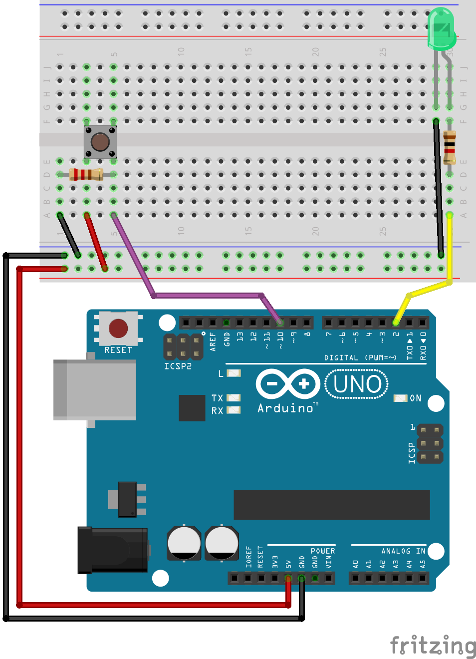
Let’s write a program that takes the button state detecting edges both rising and falling, and write it on your serial monitor 1 .
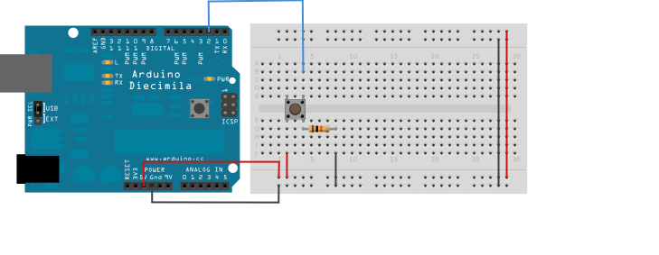
First, let’s connect the button:
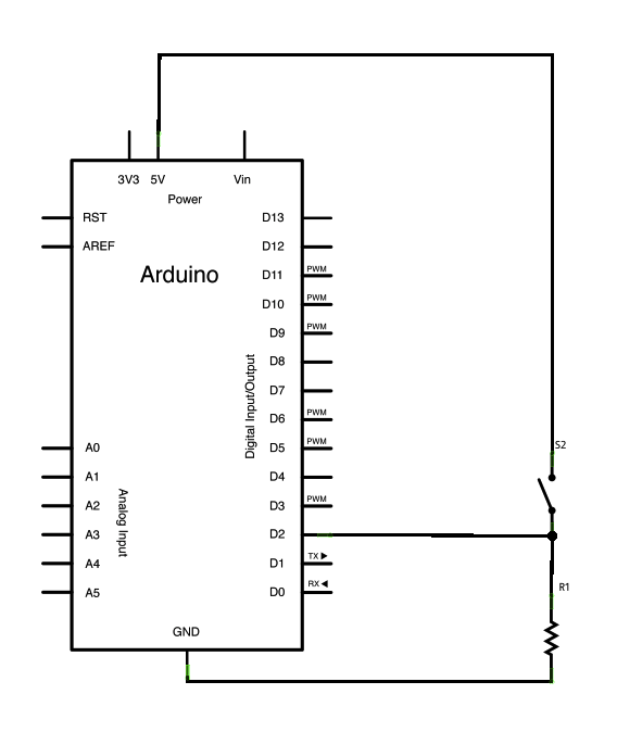
This will look like that with your breadboard and Arduino:
Generalizing the concept
The following example depicts a useful function for rising edge detection of multiple inputs.
/*
 * Check if button is pressed, i.e. if it is high, and it was low before.
 */
int buttonPressed(uint8_t digital_input) {

  static uint16_t lastStates = 0; // Store the states of digital input 0 - 15.

  uint8_t state = digitalRead(digital_input);

  if (state != ((lastStates >> digital_input) & 1)) {
    lastStates ^= 1 << digital_input;
    return state == HIGH;
  }
  return false;
}
Rough Timing in Arduino
The Arduino functions associated with timing that we will be using in this tutorial are:
Operation
The Atmega 328 has several built in hardware timers (two 8-bit and one 16-bit). These timers allow for many advanced timing applications. The Arduino library utilizes one of these timers for a counter that counts the number of microseconds since the last time the controller was restarted. Several functions are available for utilization of this counter value.
The millis() function returns the the number of milliseconds since the last time the controller was restarted. It is using a 32-bit unsigned integer to store the counter value, thus the maximum value is given by:
If we convert this value from milliseconds, to days we get:
Thus we see that the counter will wrap around after approximately 50 days. This should be accounted for in applications where the controller is running continously for extended periods of time.
The following code is excerpt from the Arduino library, and shows the implementation of the millis() function:
unsigned long millis()
{
        unsigned long m;
        uint8_t oldSREG = SREG;

        // disable interrupts while we read timer0_millis or we might get an
        // inconsistent value (e.g. in the middle of a write to timer0_millis)
        cli();
        m = timer0_millis;
        SREG = oldSREG;

        return m;
}
If higher accuracy is required there is also a micros() function, returning the number of microseconds since the last reboot.
The following code depicts the implementation of the micros() function:
unsigned long micros() {
        unsigned long m;
        uint8_t oldSREG = SREG, t;

        cli();
        m = timer0_overflow_count;
#if defined(TCNT0)
        t = TCNT0;
#elif defined(TCNT0L)
        t = TCNT0L;
#else
        #error TIMER 0 not defined
#endif

#ifdef TIFR0
        if ((TIFR0 & _BV(TOV0)) && (t < 255))
                m++;
#else
        if ((TIFR & _BV(TOV0)) && (t < 255))
                m++;
#endif

        SREG = oldSREG;

        return ((m << 8) + t) * (64 / clockCyclesPerMicrosecond());
}
In embedded systems it is often required to write code that has some delay between executing different parts of the code. For very simple applications it might be sufficient to use code that simply blocks until a given amount of time has passed. The delay() function will block for the given number of milliseconds, before execution continues.
The delay() function is implemented as a so called waste routine. It wastes execution cycles while waiting for a counter to reach zero.
void delay(unsigned long ms)
{
        uint32_t start = micros();

        while (ms > 0) {
                yield();
                while ( ms > 0 && (micros() - start) >= 1000) {
                        ms--;
                        start += 1000;
                }
        }
}
If finer control over the delay is needed, the delayMicroseconds() function may be used. The code for this function is to involved to be included here, but it is available it the official repository for Arduino
Usage
We have allready seen how the delay() function is used in the simple LED blink example. The millis() function allows us to do more interesting and useful delay implementations, where different parts of the code may execute while we are waiting for the required time to pass.
Stopwatch
#include <Arduino.h>

const uint8_t led_pin = 2;
const uint8_t button_pin = 10;

void setup() {
  // put your setup code here, to run once:
  pinMode(button_pin,INPUT);
  pinMode(led_pin,OUTPUT);
  Serial.begin(9600);

  digitalWrite(led_pin,LOW);

  Serial.println("Setup complete.");
}

void loop() {
  // put your main code here, to run repeatedly:

  static uint8_t button_past = 0;
  uint8_t button_now;
  static uint8_t timer_active = 0;
  static uint32_t start_time = 0;
  static uint32_t stop_time = 0;

  uint32_t delta_time = 0;
  float timer_seconds = 0;

  button_now = digitalRead(button_pin);

  if((button_now == 0) && (button_past == 1)){ // Falling edge is less prone to bounce

    if(timer_active == 0){
      start_time = millis();

      Serial.print("Starttid: ");
      Serial.println(start_time);

      timer_active = 1;
    }
    else{

      stop_time = millis();
      Serial.print("Stopptid: ");
      Serial.println(stop_time);

      delta_time = stop_time - start_time;

      Serial.print("Delta tid: ");
      Serial.println(delta_time);

      timer_seconds = delta_time/1000.0;
      Serial.print("Delta tid sekunder: ");
      Serial.println(timer_seconds);
      timer_active = 0;
    }
 }

  button_past = button_now;

  delay(1);
}
Assignment 1 : Real time clock
void setup()
{
   Serial.begin(9600);
}

//globale variable
int Year=2019;
int Month=1;
int Date=2;
int Hour=12;
int Minutes = 0;
int Seconds = 0;

void loop()
{
   //oppdater tidsvarable
   Seconds++; //kompakt versjon av Second = Second + 1;
   if (Seconds == 60)
   {
      Seconds = 0;
      Minutes++;
   }

   // Skriv ut verdier
   Serial.print(Hour);
   Serial.print(":");
   Serial.print(Minutes);
   Serial.print(":");
   Serial.println(Seconds);

   // vent
   delay(1000); // vent et sekund
}
Switching frequency modulation example
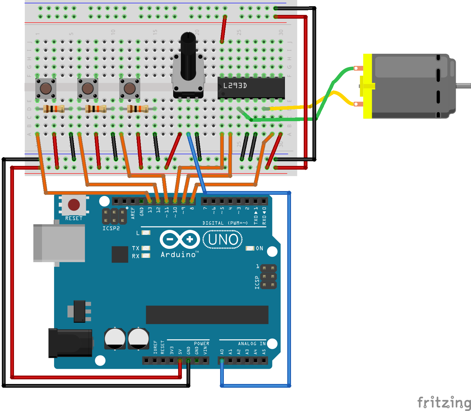
The following source code listing is the complete software for the motor drive with switching frequency control:
Show/Hide Code
#include <Arduino.h>

#include "music.h"
/*
 * The timer responsible for PWM generation on pin 5, and 6 is also used for the millis()
 * function. Thus it is not as accurate, and should be avoided if possible.
 *
 * Pins 5 and 6: controlled by Timer 0
 * Pins 9 and 10: controlled by timer 1 (16 bit timer)
 * Pins 11 and 3: controlled by timer 2
 */
const uint8_t enable1 = 10;
const uint8_t input1 = 9;
const uint8_t input2 = 8;
const uint8_t enable_button = 12;
const uint8_t direction_button = 11;
const uint8_t control_voltage = A0;


/*
 * Constants for the PWM switching frequency modulation routine.
 */
const uint8_t beats_per_minute = 96;
const uint8_t note_gap_percent = 10;

const uint32_t beat_duration_us = (60.0 / beats_per_minute) * 1000000L;
const uint32_t note_gap_us = beat_duration_us * (note_gap_percent / 100.0);

//#define DEBUG

typedef enum {
  FORWARD,
  REVERSE
} direction_t;

typedef enum {
  RUNNING,
  BLOCKED,
  STOPPED
} motor_state_t;

typedef enum {
  PLAY_NOTE,
  PAUSE_NOTE
} note_state_t;

void motor_control(uint8_t duty_cycle, direction_t direction);
int buttonPressed_debounce(uint8_t digital_input, uint8_t debounce_delay);
void set_pwm_output_10(uint8_t duty_cycle, uint16_t pwm_frequency);
void configure_timer_1();
uint16_t get_key_frequency(uint8_t key_number);

void run_motor_and_play_note(uint8_t duty_cycle);

void c_scale_test();
void c_scale_test_2();


void setup(){
  pinMode(enable1, OUTPUT);
  pinMode(input1, OUTPUT);
  pinMode(input2, OUTPUT);

  pinMode(enable_button, INPUT);
  pinMode(direction_button, INPUT);

  configure_timer_1();

  Serial.begin(9600);
}

void loop(){

  motor_state_t motor_state = STOPPED;
  direction_t motor_direction = FORWARD;
  uint8_t duty_cycle = 0;

  for(;;){

    duty_cycle = analogRead(control_voltage)/10;

    #ifdef DEBUG
    Serial.print("Duty cycle: ");
    Serial.print(duty_cycle);
    Serial.print("\n");
    delay(1000);
    #endif

    /*
     * State machine for motor control.
     */
    switch (motor_state)
    {
    case RUNNING:

      if(buttonPressed_debounce(enable_button, 50)){
        motor_state = BLOCKED;
        Serial.println("Motor blocked.");
      }

      switch (motor_direction)
      {
      case FORWARD:
        if(buttonPressed_debounce(direction_button, 50)){
          motor_direction = REVERSE;
          Serial.println("Motor direction reversed.");
        }

        motor_control(duty_cycle, FORWARD);

        break;
      case REVERSE:
        if(buttonPressed_debounce(direction_button, 50)){
          motor_direction = FORWARD;
          Serial.println("Motor direction forward.");
        }

        motor_control(duty_cycle, REVERSE);

        break;
      default:
        motor_state = STOPPED;
        break;
      }
      break;

    case BLOCKED:
      if(buttonPressed_debounce(enable_button, 50)){
        motor_state = STOPPED;
        Serial.println("Motor stopped.");
      }

      /*
       * Rotor blocking is hard to implement without any measurements. We should at least measure
       * the armature current, and estimate (or measure) the rotor position.
       *
       * This kinda works, but it is far from ideal.
       */
      _delay_us(10);
      //motor_control(100, FORWARD);
      _delay_us(10);
      //motor_control(100, REVERSE);

      break;
    case STOPPED:
      if(buttonPressed_debounce(enable_button, 50)){
        motor_state = RUNNING;
        Serial.println("Motor enabled.");
      }

      motor_control(0, REVERSE);

      break;
    default:
      motor_state = STOPPED;
      break;
    }
  }
}

void motor_control(uint8_t duty_cycle, direction_t direction){

  if(direction == FORWARD){
    digitalWrite(input1, HIGH);
    digitalWrite(input2, LOW);
  }
  else {
    digitalWrite(input1, LOW);
    digitalWrite(input2, HIGH);
  }

  run_motor_and_play_note(duty_cycle);
}

/*
 * TODO: If the motor is running backwards the music should also play backwards.
 */
void run_motor_and_play_note(uint8_t duty_cycle){

  static uint32_t start_micros = 0;
  static uint32_t note_counter = 0;
  static note_state_t note_state = PLAY_NOTE;

  uint8_t note_key_number = notes[note_counter][0];
  uint8_t note_type = notes[note_counter][1];

  uint32_t note_duration_us = beat_duration_us * (4.0 / note_type);
  uint16_t note_frequency = get_key_frequency(note_key_number);

  switch(note_state){
  case PLAY_NOTE:

    set_pwm_output_10(duty_cycle, note_frequency);

    if(micros() > (start_micros + note_duration_us)){
      note_state = PAUSE_NOTE;
    }
    break;
  case PAUSE_NOTE:

    set_pwm_output_10(duty_cycle, 4000); // A high switching frequency is used for note gaps

    if(micros() > (start_micros + note_duration_us + note_gap_us)){
      start_micros = micros();
      note_counter++;
      note_state = PLAY_NOTE;
    }
    break;
  }

  // if(micros() > (start_micros + note_duration_us)){
  //   uint16_t note_frequency = get_key_frequency(note_key_number);

  //   start_micros = micros();

  //   set_pwm_output_10(duty_cycle, note_frequency);

  //   note_counter++;

  if(note_counter > (sizeof(notes)/sizeof(*notes))){
    note_counter = 0;
  }
}

/*
 * Check if button is pressed, i.e. if it is high, and it was low before.
 * This version includes a debounce timer.
 *
 * The debounce time is stored as an array of 16 32-bit integers, thus it is
 * not very memory efficient. A better approach would be to use a object for
 * each button you wish to debounce.
 */
int buttonPressed_debounce(uint8_t digital_input, uint8_t debounce_delay) {

  static uint16_t lastStates = 0; // Store the states of digital input 0 - 15.
  static uint32_t lastEdgeDetect[16] = {0}; // Store the time of the last rising edge.

  uint8_t state = digitalRead(digital_input);


  // Check if the state of the digital input has changed.
  if (state != ((lastStates >> digital_input) & 1)) {
    lastEdgeDetect[digital_input] = millis();
  }

  if((millis() - lastEdgeDetect[digital_input]) > debounce_delay){

    lastStates ^= 1 << digital_input; // Store the current state of the digital input.

    return state == HIGH;
  }
  return false;
}

/*
 * Sets the duty cycle and switching frequency for PWM output
 * on pin 10, i.e. timer 1.
 */
void set_pwm_output_10(uint8_t duty_cycle, uint16_t pwm_frequency){

  if(duty_cycle > 100)
    duty_cycle = 100;

  configure_timer_1();

  TCCR1B |= (0 << CS12) | (0 << CS11) | (1 << CS10);

  /*
   * The 16 bit OCR1A register is double buffered, which makes it safe to update while PWM is running.
   *
   * The required compare value for a given duty cycle depends on the PWM frequency.
   */

  uint16_t top = F_CPU/((1 * pwm_frequency) - 1);
  OCR1A = top;
  uint16_t comp = (top/100)*duty_cycle;
  OCR1B = comp;

  #ifdef DEBUG
  Serial.print("TOP: ");
  Serial.println(top);
  Serial.print("COMP: ");
  Serial.println(comp);
  delay(500);
  #endif
}

void configure_timer_1(){

  TCCR1A = (1 << COM1A1) | (0 << COM1A0) | (1 << COM1B1) | (0 << COM1B0) | (1 << WGM11) | (1 << WGM10);

  TCCR1B = (0 << ICNC1) | (0 << ICES1) | (1 << WGM13) | (1 << WGM12) | (0 << CS12) | (0 << CS11) | (0 << CS10);

  TCCR1C = (0 << FOC1A) | (0 << FOC1B);
}

void c_scale_test(){

  uint8_t duty_cycle = 20;
  set_pwm_output_10(duty_cycle, 262);
  delay(500);
  set_pwm_output_10(duty_cycle, 294);
  delay(500);
  set_pwm_output_10(duty_cycle, 330);
  delay(500);
  set_pwm_output_10(duty_cycle, 349);
  delay(500);
  set_pwm_output_10(duty_cycle, 392);
  delay(500);
  set_pwm_output_10(duty_cycle, 440);
  delay(500);
  set_pwm_output_10(duty_cycle, 493);
  delay(500);
  set_pwm_output_10(duty_cycle, 523);
  delay(2000);

}

void c_scale_test_2(){

  uint8_t duty_cycle = 20;

  set_pwm_output_10(duty_cycle, get_key_frequency(40));
  delay(500);
  set_pwm_output_10(duty_cycle, get_key_frequency(42));
  delay(500);
  set_pwm_output_10(duty_cycle, get_key_frequency(44));
  delay(500);
  set_pwm_output_10(duty_cycle, get_key_frequency(45));
  delay(500);
  set_pwm_output_10(duty_cycle, get_key_frequency(47));
  delay(500);
  set_pwm_output_10(duty_cycle, get_key_frequency(49));
  delay(500);
  set_pwm_output_10(duty_cycle, get_key_frequency(51));
  delay(500);
  set_pwm_output_10(duty_cycle, get_key_frequency(52));
  delay(2000);

}

uint16_t get_key_frequency(uint8_t key_number){

  if((key_number >= 1) && (key_number <= 88)){
    uint16_t keyfreq = (pow(2.0, (key_number - 49.0)/12.0) * 440.0); // Compute the frequency for a given piano key.
    return keyfreq;
  }

  return 0;
}
Arduino math functions
The Arduino library comes with several useful math functions. Some of these are almost self explanatory, while others may require some explaning. As always the best place to start looking for information about the Arduino built in functions is the Arduino language reference
abs()
constrain()
map()
max()
min()
pow()
sq()
sqrt()
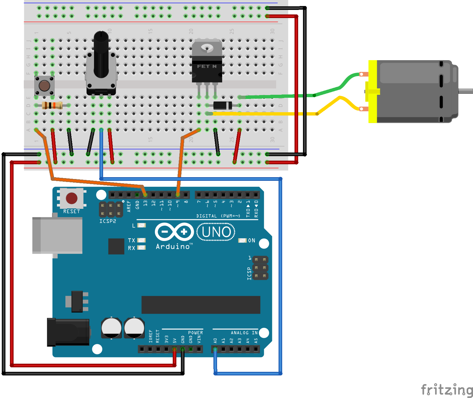
Simple motor drive example with speed control
The function analogWrite() will be used to generate a PWM signal to the transistor, and the switching frequency will stay at it’s default value. A analog signal input on A0 will be used to control the duty cycle of the PWM, and hence the torque (and consequently the speed) of the motor.
#include <Arduino.h>

const uint8_t pwm_pin = 9;
const uint8_t on_off_button = 12;
uint8_t old_button_state = 0;
uint8_t motor_enable = 0;

void setup() {
  pinMode(pwm_pin, OUTPUT);
  pinMode(on_off_button, INPUT);

  Serial.begin(9600);
}

void loop() {

  uint8_t button_state = digitalRead(on_off_button);
  if(button_state != old_button_state){

    old_button_state = button_state;

    // TODO: This code requires debouncing of the push button.
    if(button_state == 1){

      if(motor_enable == 1){
        Serial.println("Motor disabled.");
        analogWrite(pwm_pin, 0);
        motor_enable = 0;
      }
      else {
        Serial.println("Motor enabled.");
        analogWrite(pwm_pin, 100);
        motor_enable = 1;
      }
    }
 }


}
Footnotes
- 1
Source code as arduino.cc DigitalReadSerial