Analog output (digital to analog conversion)
Real world and Arduino world works different. In this world everything you experience are continuous. What you see, what you hear, what you speak, what you taste and smell. However, the Arduino world is discrete. Everything happening are defined with 1s and 0s.
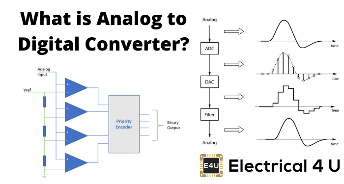
Source: https://www.electrical4u.com
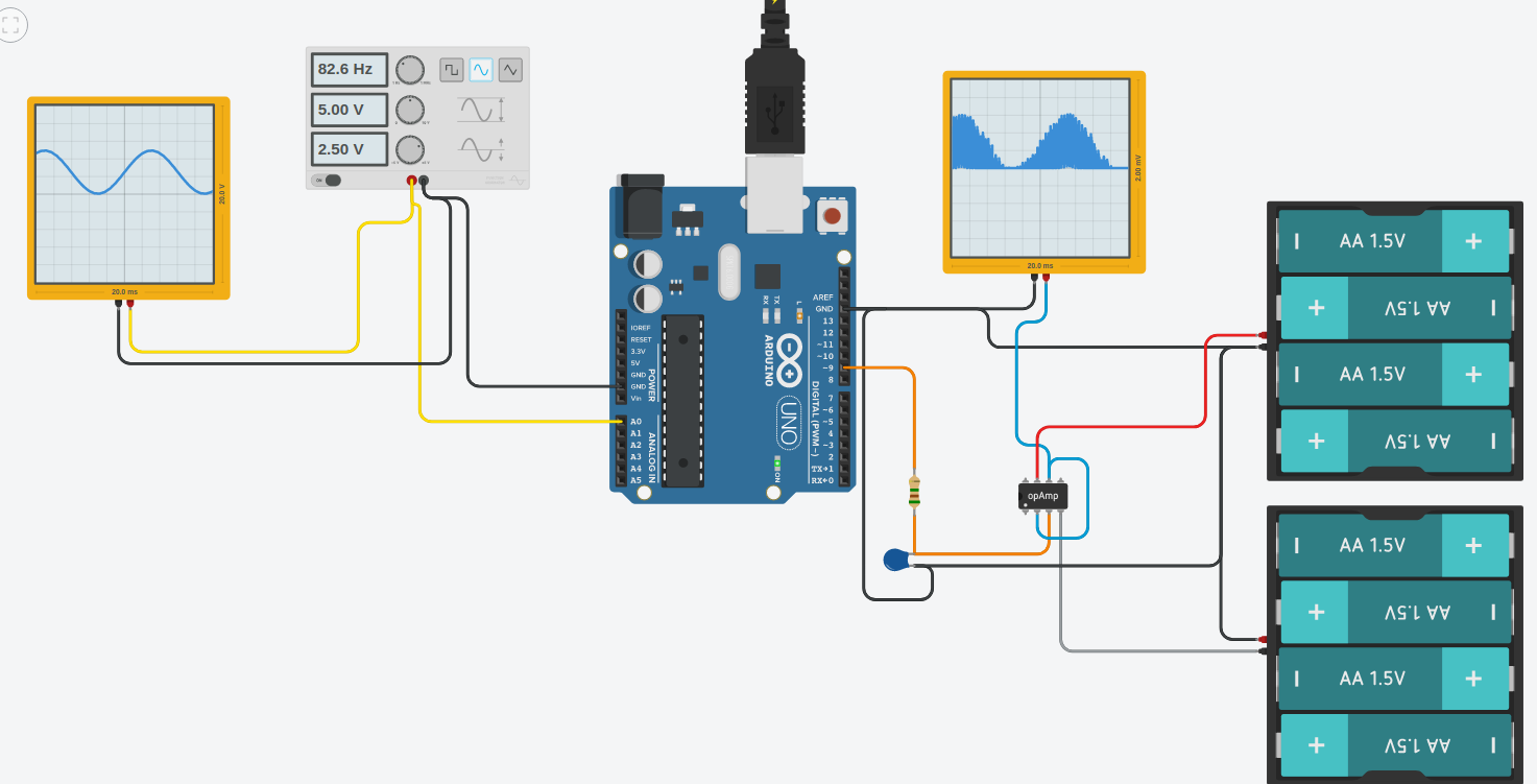
Source: ADC DAC in Arduino (by Ruzo)
In this lecture, we will talk about how to convert something digital into something analog.
Digital to analog converter
A digital to analog converter is a device which converts a digital representation of a signal in to a real physical signal, typically a voltage. The digital representation is just a number, which has discrete steps in it’s value, while the analog signal is capable of continuous variation 1.
See also
Language is discrete, feelings are not
One may think about this analog-digital trade off as an art of categorization. When I say everything in this world is continuous, I mean it. Let’s do a bit psychological brainstorming, shall we? Think about your feelings. When you experience something that makes you happy, you describe/express it with a word: Happy. What if you are really happy? Well, you can emphasize your word (very happy) or categorize and redefine your happiness with another word: Amused. If that’s not enough, you can always increase your precision: (very amused) or thrilled.
What is important in here is not the language but the limitation of the language (which has a discrete characteristics) when you want to express your feelings (which has a continuous characteristics). It is never the exact representation of what really feel when you speak it out. This leads me to the conclusion that you will always lose when you trade off between analog and digital.
Digital to Analog Conversion of feelings. The language is discrete.
So, you can think about expressing your feelings with words as ANALOG-TO-DIGITAL conversion. Understanding what someone feel when they told you as DIGITAL-TO-ANALOG conversion.
Pulse Width Modulation (PWM)
Let’s go back to the Arduino world. There is NO ANALOG OUTPUT in Arduino. What? What about analogWrite() ?
We need to talk.
What is Modulation?
What is a pulse?
PWM and duty cycle
There are two primary components that define a PWM signal’s behavior:
Duty cycle: A duty cycle is the fraction of one period when a system or signal is active. We typically express a duty cycle as a ratio or percentage. A period is the time it takes for a signal to conclude a full ON-OFF cycle.
Frequency: The rate at which something repeats or occurs over a particular period. In other words, the rate at which a vibration happens that creates a wave, e.g., sound, radio, or light waves, typically calculated per second.
Question: How does the frequecy of the PWM signal affect the produced analog signal?
Analog output by PWM
As already discussed, analog output from a microcontroller (or any digital system) is performed by means of a Digital to Analog Converter (DAC). The Atmega328p of the Arduino UNO does not have a dedicated DAC built in to the device, but it has another feature which allows us to perform a crude digital to analog conversion 2. The feature is known as pulse width modulation, and basically means that we are switching one of the digital outputs on and off quickly, but with variation in the durations the output stays high and low. This allows us to control the average output voltage. By using some external components for filtering, this pulsating voltage can be converted to a steady voltage with a value corresponding to the average of the PWM signal.
You may wonder why pulse width modulation is a special feature in the microcontroller, only available on some pins. As you know from the previous lessons, any GPIO pin is capable of switching between the two voltage states representing high, and low (5 V, and 0 V on the Arduino UNO). It is indeed possible to generate PWM on any GPIO, and there are examples on situations where switching a generic GPIO in this way is desirable. The problem is that this switching is controlled by the software, taking up a certain amount of the available CPU time. If the switching frequency is supposed to be high, it will leave little room for the microcontroller to be working on other tasks besides the PWM. Additionally having multiple PWM outputs in this way increases the load even further. For this reason dedicated hardware support for PWM in included on some pins of the microcontroller. You simply configure the PWM, and the output will be running continuously with your settings, until it is changed from software. The reason only some pins have PWM is simply to reduce cost, there are other more powerful microcontrollers which support PWM on any pin.
Alternatively if you need “real” analog output you may use an external chip (such as MCP4725 12-Bit DAC, that the Arduino may control by a digital bus such as I2C.
Operation of a pulse width modulator
In this section we will cover the basics of how the PWM-outputs on the Atmega328p are operating.
The Arduino function associated with analog output signals that we will be using in this tutorial are:
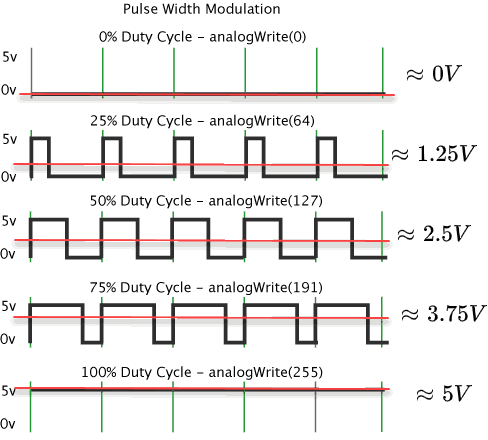
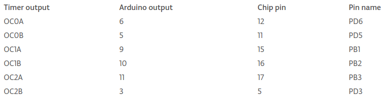
The function in the Arduino library used to output a PWM signal is analogWrite(pin, value). pin is the pin number used for the PWM output. value is a number proportional to the duty cycle of the signal. When value = 0, the signal is always off. When value = 255, the signal is always on. On the Arduino UNO, the PWM function is available on pins 3, 5, 6, 9, 10, and 11. The frequency of the PWM signal on most pins is approximately 490 Hz. On the Uno and similar boards, pins 5 and 6 have a frequency of approximately 980 Hz. Pins 3 and 11 on the Arduino Leonardo also run at 980 Hz. The Arduino library does not support changing this frequency, but it is possible to do so by directly manipulating the registers of the Atmega328p hardware.
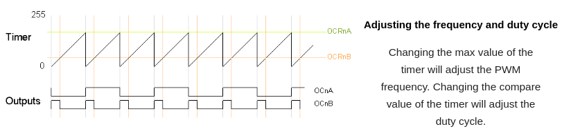
PWM adjusting the frequency and duty cycle.
PWM outputs on Arduino and Atmega328
See also
PWM is a complex topic and requires a good understanding of the microcontroller that you are working with. The analogWrite() makes the life easier for you but it is important to know that the PWM produced by this command is not the only PWM type exist. By manipulating the timers and registers in your microcontroller, you can obtain various PWM signals. Two main PWM techniques are:
Fast PWM: In the simplest PWM mode, the timer repeatedly counts from 0 to 255. (aka Edge-aligned)
Phase-Correct PWM: In this mode, the timer counts from 0 to 255 and then back down to 0. (aka Center-aligned)
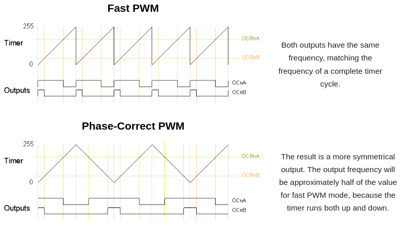
PWM modes. See more at secrets of Arduino PWM.
Please see that in fast PWM when the duty cycle changes, the center position of the pulse changes position (therefore the phase changes). With phase correct PWM when the duty cycle changes, the center position of the pulse remains constant (and therefore the phase remains constant). This is particularly important in fine DC-motor speed regulations, sound signal producing etc. where you don’t want sharp edges on your sampled signal. On the other hand, sharp edges are almost a must in servo-motor control.
Mapping signals with different dynamic range
Suppose your input signal has a range of 0 - 1023, and you need to drive the PWM which expects a value of 0 - 255. The larger dynamic range input signal needs to be mapped to the low dynamic range parameter of the PWM control signal. In order to achieve this one may use the following generic equation, where x is the input, and y is the output signal:
For our example, this yields:
The Arduino library has a built in function for the mapping of one signal over to another with a different range. But as you have seen from the above example it might be just as easy to do the calculations on your own. Anyway the function definition in the library is as follows:
long map(long x, long in_min, long in_max, long out_min, long out_max)
    {
      return (x - in_min) * (out_max - out_min) / (in_max - in_min) + out_min;
    }
Hence to map an analog input value, which ranges from 0 to 1023 to a PWM output signal, which ranges from 0 - 255, you can use the map(value, 0, 1023, 0, 255) function. This function has five parameters, one is the variable in which the analog value is stored, while the others are 0, 1023, 0 and 255 respectively.
The long variable type used it the function has the same size as int32_t.
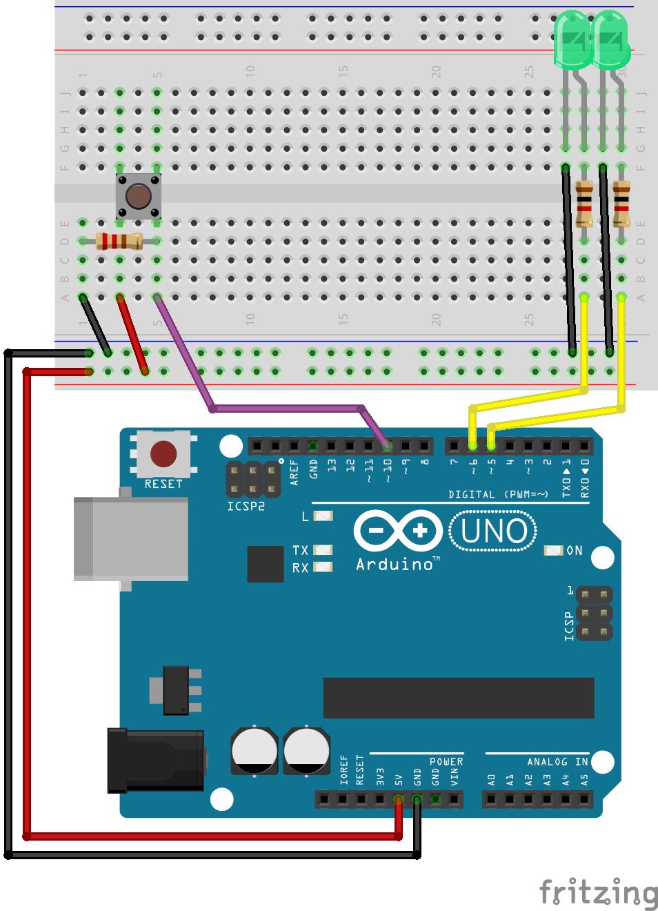
Exercise: Adjusting the light intensity of LED
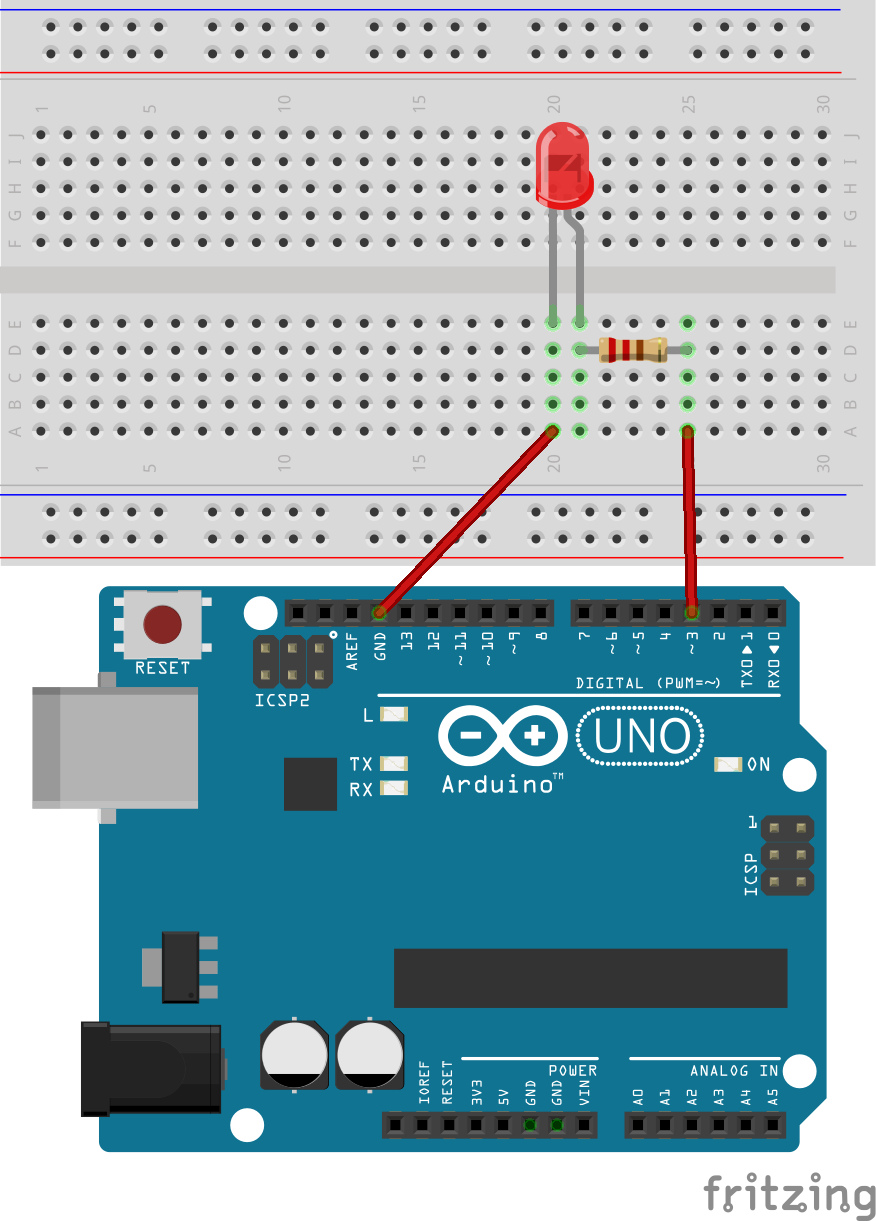
In this exercise we will adjust the light intensity of a single LED by means of PWM.
Connect a LED in accordance with the figure. If you already have a LED connected, you only have to make sure it is connected to one of the pins which support PWM.
Write a simple test program where
analogWrite(pin, value)is used to control the pin connected to the LED. Try with various values for thevalue, e.g. 64, 128, 255.Extend the program so that a digital input connected to a push button changes the intensity of the LED. When you push the button it should change the duty-cycle from 64, to 128.
Exercise: Continuously adjusting the light intensity of LED
Write a program which increase the light intensity by pushing button 1, and decrease by pushing button 2.
Exercise: Adjusting the light intensity of multiple LEDs
In this example we will be adjusting the light intensity of two LED’s connected to pin 5, and 6. A push button on pin 10 is used to step through various intensity levels.
Note
Logic Analyzer, or scope demonstration.
Todo
Add solution after the lecture
Connect the push button, and the two LEDs in accordance with the schematic.
Write a program which toggles evenly between 5 levels of light intensity (from 0 to 255) by the pushing of the button. Both LEDs should have the same intensity, starting at 0, and ending at 255.
Extend the program such that after reaching maximum intensity, another push of the button resets the intensity back to 0.
Extend the program such that while one LED is stepping down, the other is stepping up in intensity. After reaching maximum (or minimum) intensity, the direction should change.
Functions
Functions are used to organize the actions performed by your software into functional blocks. Functions package functionality into well-defined inputs (information given to a function) and outputs (information provided by a function) that make it easier to structure, maintain, and reuse your code. You are already familiar with the two functions that are in every Arduino firmware: setup and loop. You create a function by declaring its return type (the information it provides), its name, and any optional parameters (values that the function will receive when it is called). 3
Note
The terms functions and methods are used to refer to well-defined blocks of code that can be called as a single entity by other parts of a program. The C language refers to these as functions. Object-oriented languages such as C++ that expose functionality through classes tend to use the term method. Arduino uses a mix of styles (the example sketches tend to use C-like style, libraries tend to be written to expose C++ class methods). We will normally use the term function, unless the code is exposed through a class. Don’t worry; if that distinction is not clear to you, treat both terms as the same.
A parameter is sometimes referred to as an argument in some documentation. For practical purposes, you can treat these terms as meaning the same thing. We will use them interchangeably here.
No input no output
In mathematic a function which takes no input, and provide no output makes no sense. In our software however it does make sense because here a function can have side effects. I.e. it can affect something outside of the function call, such as a digital output, a memory location, or it can simply block forcing us to wait for a while. E.g. a function delay_one_second() could be defined which block for one second (though we would not recommend this, or consider it a good practice).
Actually, even if the function takes no parameters, the function call can be considered the simples possible parameter. The call will happen on a specific instant in your code, and this will affect the instant at which the side effects of the function.
const int ledPin = 2;

void setup() {
    Serial.begin(9600);
    pinMode(ledPin, OUTPUT);
}

void loop() {
    my_func_on();
    delay(500);
    my_func_off();
    delay(500);
}

void my_func_on(){
    digitalWrite(ledPin, HIGH);
}

void my_func_off(){
    digitalWrite(ledPin, LOW);
}
No output but with input
const int ledPin = 2;
bool ledState = false;

void setup() {
    Serial.begin(9600);
    pinMode(ledPin, OUTPUT);
}

void loop() {
    my_func(ledState);
    ledState = !ledState;
    delay(500);
}

void my_func(bool state){
    digitalWrite(ledPin, state);
}

void my_nosense_func(int a){
    a = 5;
}
Integer return
The following code demonstrate how to define a function which is capable of returning a single integer. It is a silly function which always returns 5, regardless of what value you try to pass as a parameter.
int my_meaningful_func(int a){
    a = 5;
    return a;
}
The basic functions in C are only able to return a single value. You can return multiple values but it is a bit more advanced topic which require utilizing some features on the language which we have not discussed so far.
Exercise: Abstracting away your hardware
In order to make it easy to reuse your code on multiple platforms, it can be useful to use functions to abstract away you hardware. E.g. instead of running digitalWrite(red_led, HIGH) when you need to change a digital output for a LED, it is better to define a separate function red_led_on(); which perform this operation.
void red_led_on(){
    digitalWrite(red_led, HIGH)
}
If you move to a different platform instead of Arduino, it is likely that the function which modify a digital output will be different. E.g. on the STM32 HAL the function is HAL_GPIO_WritePin(GPIOA, RED_LED_PIN, GPIO_PIN_SET);. For a large software project you could easily be modifying the state of the LED in multiple areas of your code. Thus there will me many places you would have to change. If you have abstracted the operation by a function however, the only place you have to change your code is inside this special function.
Start by copying the switch debounce example discussed previously in to a new project.
Modify the program so that it toggles the state of a LED when a button is pushed.
Modify the program so that it toggles the state of a LED by use of two functions,
red_led_on(), andred_led_off(). I.e. one function which turns on the LED, and another which turns it off.Add another function
red_led_toggle()which toggles the state of the LED. Update your software to use this new function.
Exercise: Pythagoras
Declare, and define a function which computes the hypotenuse of a right angled rectangle given the length of the two other sides. The function should take two arguments of type integer, and return a single integer result.
Test the function with some data, and print the result to the serial port.
Exercise: Tilt detection
In this exercise we are going to utilize a 4-pin tilt sensor to detect the orientation of the Arduino board. It is possible to detect the direction of orientation by checking which of the 4 pins are connected, but for this exercise you should only check if the switch is oriented in such a way that no pins are connected.
The datasheet for the tilt sensor is available at: https://www.arduino.cc/documents/datasheets/TiltSensor.PDF
Connect the sensor to a digital input.
Write a function which checks the state of the orientation switch. The function should return 1 (true) if the board is tilted.
Complete the application with the required code to print a message to the serial port when the board is tilted.
Function for debounce of multiple push buttons
The previously discussed method for software switch debounce is a good candidate for placement in a function. Switch debounce is almost always needed when using mechanical push buttons on digital inputs, and it makes sense to have the code available for easy reuse. Additionally if designed properly a single function can be used for debounce of multiple digital inputs.
The following source code listing illustrates how to perform multiple switch debounce in a slightly more elegant way than simply duplicating the single switch debounce code for each new button. Additionally the example illustrates the use of functions for checking for button events.
Note
It is possible to improve this example by using some advanced features of the C language, i.e. it does not need all the repetitive code in all the btnx_press_event() functions. This will have to wait for a future lecture however.
Note
Switch debouncing will be needed in almost every application which utilize push buttons. Hence you should settle upon some code which is easy to reuse for all you debouncing needs, and simply copy it in to the projects which need it.
  1#include <Arduino.h>
  2
  3const uint8_t btn1 = 5;
  4const uint8_t btn2 = 4;
  5const uint8_t btn3 = 3;
  6
  7// Check the button states with a 10 ms time interval
  8const uint8_t btn_sample_interval = 10;
  9
 10uint32_t prev_time_stamp = 0;
 11
 12uint8_t btn_asserted = 0;
 13uint8_t btn_asserted_prev = 0;
 14
 15/**
 16 * @brief Debounce up to 8 digital inputs
 17 *
 18 * This function must be called at regular intervals
 19 *
 20 * @param current_state
 21 * @return uint8_t
 22 */
 23uint8_t switch_debounce(uint8_t current_state){
 24
 25    static uint8_t asserted = 0x00;
 26    static uint8_t prev_state = 0x00;
 27
 28    btn_asserted_prev = asserted;
 29
 30    // Set the bits for the pressed buttons
 31    asserted |= (prev_state & current_state);
 32
 33    // Clear the bits for the released buttons
 34    asserted &= (prev_state | current_state);
 35
 36    // Update the history
 37    prev_state = current_state;
 38
 39    // Exclusive or between previous and current assertion
 40    // Only the bits which are different will stay high
 41    btn_asserted_prev ^= asserted;
 42
 43
 44    return asserted;
 45}
 46uint8_t btn1_press_event(){
 47
 48  if(btn_asserted_prev & 0x01){
 49
 50    if(btn_asserted & 0x01){
 51      return 1;
 52    }
 53  }
 54
 55  return 0;
 56}
 57
 58uint8_t btn1_release_event(){
 59
 60  if(btn_asserted_prev & 0x01){
 61
 62    if(!(btn_asserted & 0x01)){
 63      return 1;
 64    }
 65  }
 66
 67  return 0;
 68}
 69
 70uint8_t btn2_press_event(){
 71
 72  if(btn_asserted_prev & 0x02){
 73
 74    if(btn_asserted & 0x02){
 75      return 1;
 76    }
 77  }
 78
 79  return 0;
 80}
 81
 82uint8_t btn3_press_event(){
 83
 84  if(btn_asserted_prev & 0x04){
 85
 86    if(btn_asserted & 0x04){
 87      return 1;
 88    }
 89  }
 90
 91  return 0;
 92}
 93
 94void setup() {
 95  pinMode(btn1, INPUT);
 96  pinMode(btn2, INPUT);
 97
 98  Serial.begin(9600);
 99}
100
101void loop() {
102
103  uint32_t current_time_stamp = millis();
104
105  // Limit how often the button state is checked
106  // This method is not good if it is important to detect the first edge of the button change
107  if(current_time_stamp - prev_time_stamp > btn_sample_interval){
108
109    uint8_t btn1_state = !digitalRead(btn1);
110    uint8_t btn2_state = !digitalRead(btn2);
111    uint8_t btn3_state = !digitalRead(btn3);
112
113    btn_asserted = switch_debounce(btn1_state | (btn2_state << 1) | (btn3_state << 2));
114
115    if(btn1_press_event()){
116      Serial.println("btn1 press event.");
117    }
118
119    if(btn1_release_event()){
120      Serial.println("btn1 release event.");
121    }
122
123    if(btn2_press_event()){
124      Serial.println("btn2 press event.");
125    }
126
127    if(btn3_press_event()){
128      Serial.println("btn3 press event.");
129    }
130
131    prev_time_stamp = current_time_stamp;
132  }
133}
The example is built around the following function, which probably needs some explaining:
uint8_t switch_debounce(uint8_t current_state){

    static uint8_t asserted = 0x00;
    static uint8_t prev_state = 0x00;

    btn_asserted_prev = asserted;

    // Set the bits for the pressed buttons
    asserted |= (prev_state & current_state);

    // Clear the bits for the released buttons
    asserted &= (prev_state | current_state);

    // Update the history
    prev_state = current_state;

    // Exclusive or between previous and current assertion
    // Only the bits which are different will stay high
    btn_asserted_prev ^= asserted;

    return asserted;
}
The function is called periodically by:
btn_asserted = switch_debounce(btn1_state | (btn2_state << 1) | (btn3_state << 2));
The function takes one uint8_t as parameter. Each bit in this byte corresponds to a digital input which we want to debounce. In the function call the parameter is formed of the three bits which indicate the state of the three push buttons. We are using the bit left shift operator << to shift the bits of the button 2, and button 3 state, one, and two places respectively. The bitwise or operator | is then used to merge them in to a single byte.
After declaring some variables, the first line of interest is the following:
btn_asserted_prev = asserted;
The purpose it to store the previously asserted button states. I.e. the asserted variable holds the state (which is considered stable) of up to 8 push buttons, and before we update it, we first store the previous value.
The next statement is the following:
asserted |= (prev_state & current_state);
The purpose is to compare the previous state of the push buttons to the current state. If the states are equal, and high, we set the corresponding bits in the asserted variable.
After setting the bits of the inputs that are high (and stable), we should also clear the inputs which are low (and stable). This is performed by the following statement:
asserted &= (prev_state | current_state);
We use the bitwise or operator | to make sure that only the bits which are zero in both the current, and previous state will be asserted as low.
Further down we update the history in preparation for the next time the function is called:
prev_state = current_state;
Finally we use the bitwise exclusive or operation ^ between the currently asserted button states, and the previously asserted button states. This has the effect that only the bits that are different (the buttons which have changed state) remains high in btn_asserted_prev. By checking the states of these bits, we can then determine if a button has changed state or not.
btn_asserted_prev ^= asserted;
This variable is then used to detect the state change of a given input (0x04 = 0b100), input 3 in this example:
if(btn_asserted_prev & 0x04){
Loops
Loops are the mechanism by which our software is able to perform repetitive tasks. We have already been using a loop, our loop() function. This loop is known as an infinite loop, as there is no condition in our software which will make it stop. Ofc it will stop if you reset your controller, or remove the power supply, but such conditions are outside the control of our software. Infinite loops are useful in application which should be performing some operation constantly, e.g. in order to be responsive to external events.
For many applications however it is useful to have a loop which only execute the same code a limited number of times. This could be a given fixed number of times, or there could be some condition which will make the loop stop.
While loops
The while loop executes as long as the condition inside the parentheses is true.
while(condition){

}
For loops
The for loop execute as long as a condition is true, but unlike the while loop it has a slightly more organized structure for counting. There is nothing the for loop can do, which the while loop can not do, but it can make your code more clean.
The following example illustrates the use of the for loop for executing the same code 10 times.
for(uint8_t i = 0; i < 10; i++){
    // Add code to execute here
}
If you want to use a while loop to perform the same task, you would have to write:
uint8_t i = 0;
while(i < 10){
    i++;
    // Add code to execute here
}
In the for loop the counter variable i is updated after the code inside the loop is executed, hence if the counter variable is used by the code and you want the exact same operation as the for loop example, you must do the following:
uint8_t i = 0;
while(i < 10){
    // Add code to execute here
    i++;
}
That is you must place the code that you are going to add above the increment of the counter (in the above code only the comment is moved).
Do while loops
The do while loop is likely the least commonly used of the three types we discuss here. The difference between while, and do while, is that the latter is executed at least once. Again there is nothing preventing you from achieving the same result by using while, or for loops, but in some situations the do while loop will produce the most clean code.
For our count to 10 example we can do:
uint8_t i = 0;
do {
    // Add code to execute here
    i++;
} while(i < 10);
Loop example
The following code listing demonstrate the three loop types discussed in the previous sections. As a bonus a fourth loop type based on the goto keyword is also demonstrated, but this type is rarely used in practice.
 1#include <Arduino.h>
 2
 3void while_loop_test(){
 4
 5  uint8_t i = 0;
 6
 7  while (i < 10)
 8  {
 9    Serial.print("While loop: ");
10    Serial.println(i);
11    i++;
12  }
13}
14
15void for_loop_test(){
16
17  for(uint8_t i = 0; i < 10; i++)
18  {
19    Serial.print("For loop: ");
20    Serial.println(i);
21  }
22}
23
24void do_while_loop_test(){
25
26  uint8_t i = 0;
27
28  do {
29    Serial.print("Do while loop: ");
30    Serial.println(i);
31    i++;
32  } while (i < 10);
33}
34
35/**
36 * Note: unless you are absolutely sure that it is the right choice it is better to avoid the goto/label approach.
37 * It is somtimes used for error handling, but rarely a good choice for loops.
38 */
39void goto_loop_test(){
40  uint8_t i = 0;
41
42  loop_label:
43    Serial.print("goto loop: ");
44    Serial.println(i);
45    i++;
46
47  if(i < 10){
48    goto loop_label;
49  }
50}
51
52void setup() {
53  Serial.begin(9600);
54}
55
56void loop() {
57
58  while_loop_test();
59  for_loop_test();
60  do_while_loop_test();
61  goto_loop_test();
62
63  delay(10000);
64}
65
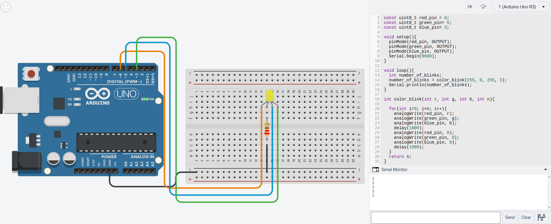
Exercise: Blink a colorful LED n-times
No copy paste this time. Can you make this to work? Observe different colors.
Exercise: Blink a colorful LED n-times with user input
Extend the previous example by asking the user how many times s/he wants the LED to blink. Instead of printing the total number of blinks, print out the blink number in every iteration.
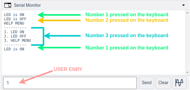
Exercise: Serial UI for LED control
Let’s design a serial UI for controlling the button state.
Design requirements:
An LED is connected to pin number 3 will be controlled by keyboard inputs.
The user is allowed to enter 1, 2 and 3 as input. If something else is entered, a help manual will appear.
Keyboard number 1 will turn on the LED.
Keyboard number 2 will turn off the LED.
Keyboard number 3 will give the help manual as shown in the figure.
Note
The rx_byte = Serial.read(); will be useful.
Footnotes
- 1
In reality the digital representation is also analog. It is analog in the sense that the computer exists in a analog universe, but it does not matter if the computer uses 0 V and 5 V, 0 V and 3.3 V, or some other voltage levels to represent the binary values. Either way the interpretation of the digital value should be the same.
- 2
In reality the PWM DAC does not necessarily have to be considered a crude way to convert from digital to analog. It all depends on the switching frequency, and the analog filtering which is applied.
- 3
Arduino Cookbook by Michael Margolis Chapter 2.