Digital I/O, and timing
Using digital inputs
Digital inputs have already been covered in detail in a previous lesson. In this lesson the focus is on how to best utilize the digital input signal in software.
Edge detection
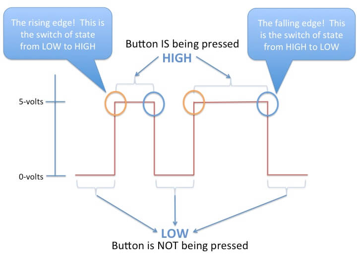
When reading a digital input it is often desirable to determine the instant it is changing, and how it is changing. I.e. whether it is a rising, or a falling edge. There are several approaches we can take to solve this problem, but in this section we focus on solutions involving the sampling of the digital input. I.e. we are continuously checking the state of the digital input with a certain time interval. This approach is fine for slowly changing signals such as push buttons. Actually it is not only fine, it is often the recommended way to deal with slow signals.
In order to detect the rising edge of a digital input by the sampling method, we continuously compare the current state of the input, to the state at the previous iteration (the previous time we checked it). If the previous value was low, and the current value is high, we have a rising edge. The same logic can be applied it the reverse direction to detect the falling edge.
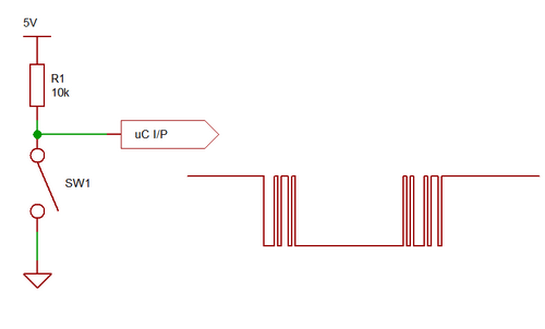
Let’s think about what happens when you press a button. In this example (and the last) we have a digital pin connected to 5 volts through a tilt sensor. When the system is vertical, two pins are in contact. The 5 volts is applied to the digital pin. However, when you tilt the system, the connection is broken. Therefore, the system is not in OFF state but in an unknown state. Consider the figure below:
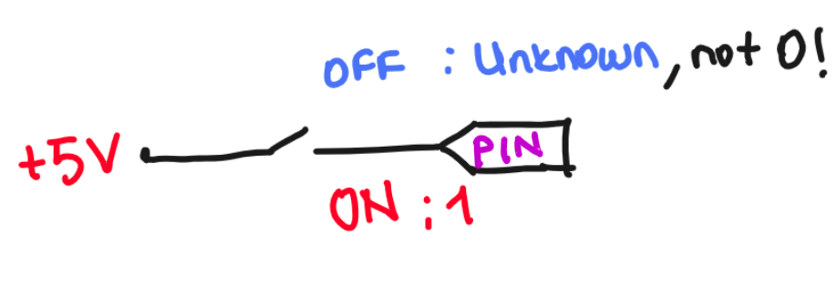
Source: programmingelectronics.com
Understanding Pull-up / Pull-down resistors
As already discussed in terms of push buttons, when using digital inputs it is often required to add resistors to either pull up, or pull down the potential at the input. This is required because the input impedance of the digital input is very high, and the state may change randomly if it is not forced to a known state. For our convenience the Atmega 328 used in the Arduino UNO has internal pull up resistors that may be enabled or disabled in software. Alternatively you may add external resistors.
The size of the resistors is not critical, but it should not be selected on random either. A to small resistor may cause excessive current, while a to large resistor will defeat the purpose of trying to pull towards a given potential. I.e. the resistor value should be far away from the value of the input impedance. In practice a 10k resistor is often used.
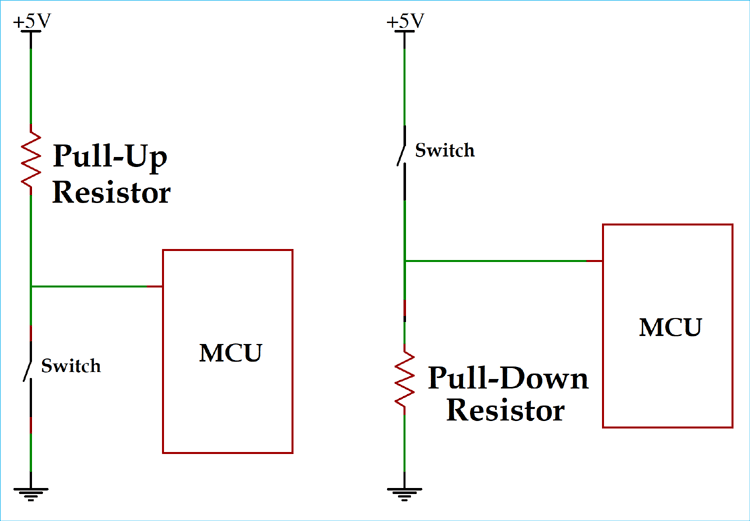
Source: circuitdigest.com
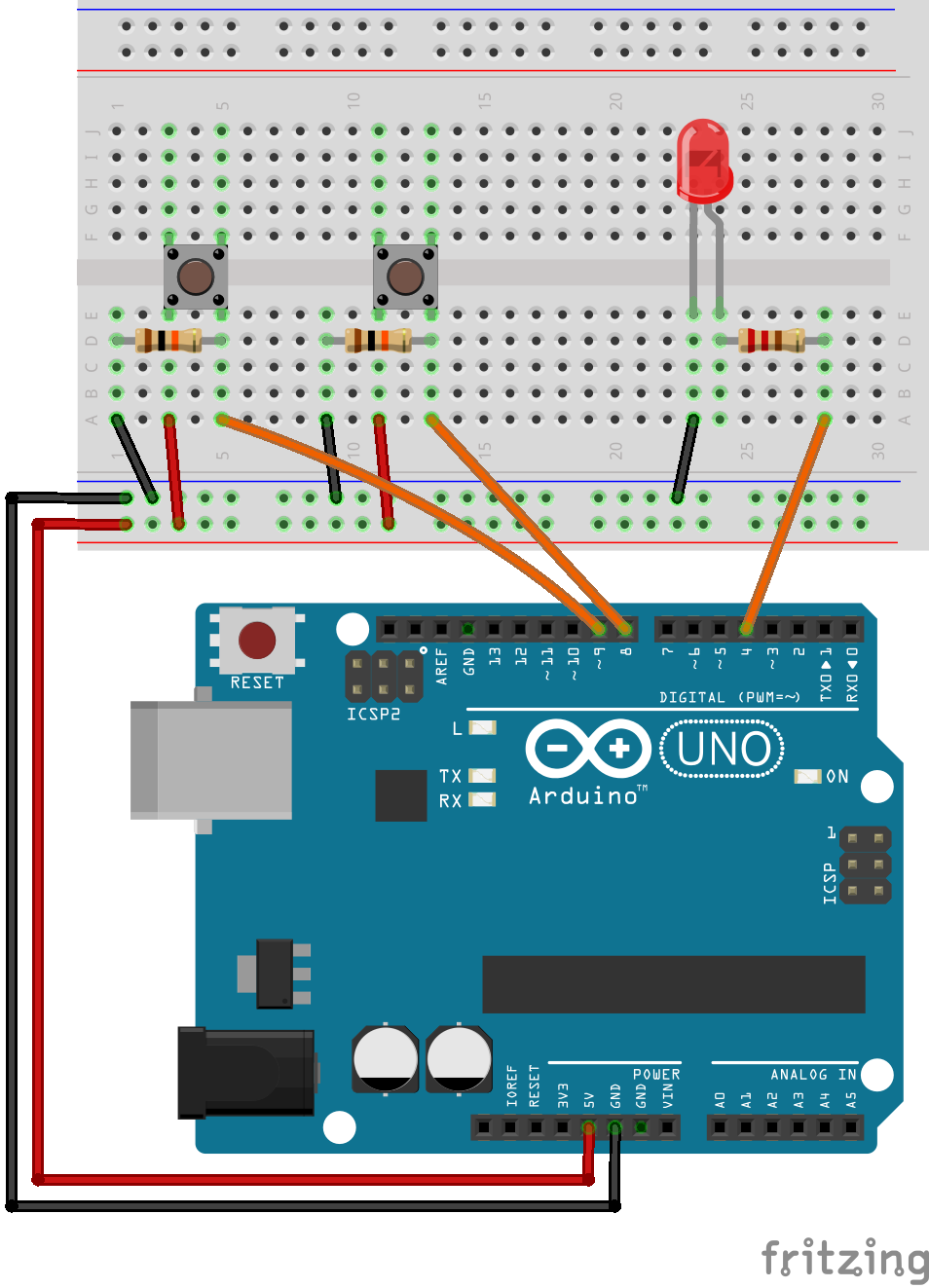
The following figure depicts the connection of two push buttons to the Arduino. For the leftmost button the resistor in the figure pulls the input low, and the push button is connected in such a way that it can pull it up. For the button to the right the configuration is opposite.

It is very important to realize that the default state of a digital input depends on whether the input is pulled up, or pulled down. If the input is pulled down by a resistor, and the push button pulls it up, then a push on the button will make the input logical HIGH. If on the other hand the input is pulled up by a resistor, and a push on the button pulls it down, pushing the button will make the input logical LOW
It is not important which of the two you choose, because it is easy to invert the state in software. But it is important to realize the difference, in order to know when you have to invert it in software.
Edge detection algorithm
Todo
Describe a typicall edge detection algorithm
Simple button press counter
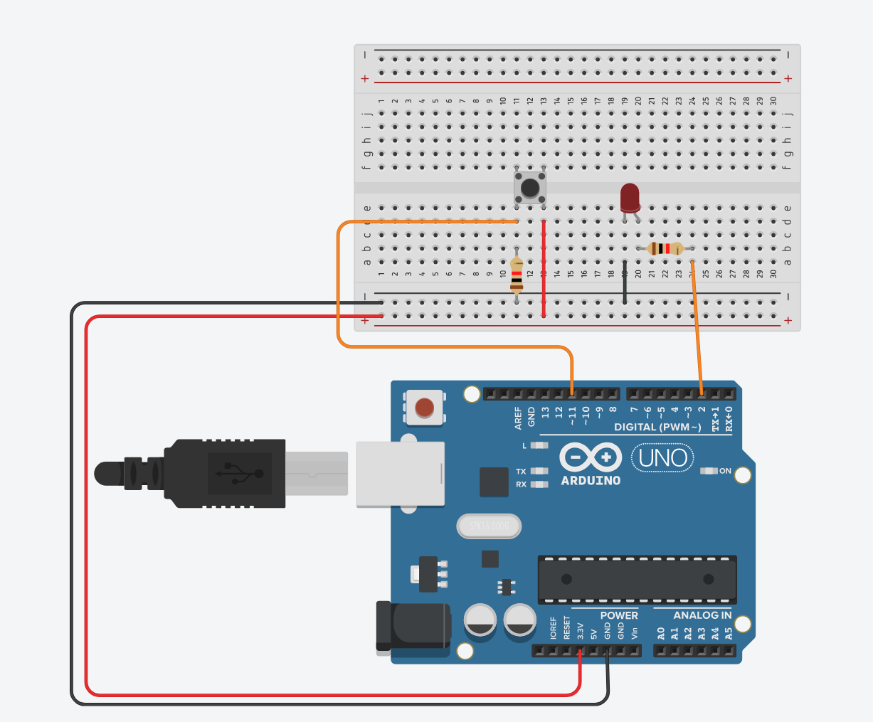
Imagine that you develop a system that counts how many times a button pressed. It can be on a secure door, a keyboard software or a simple knitting row counter! Here is a simple system:
Here is the code template:
// define led_pin at pin nr.2;
// define button_pin at pin nr.11;
// define a counter variable
void setup()
{
    // set input/output pin modes
    // start a serial communication between Arduino and the PC
}

void loop()
{
    // read button value and keep it in a variable
    // increase the counter variable
    // change the LED state accordingly
    // Print the button state and the total count on the same line with a *tab* space
    delay(10);
}
The following code listing is one possible solution:
const uint8_t led_pin = 2;
const uint8_t button_pin = 11;
uint16_t count = 0;
void setup()
{
    pinMode(led_pin, OUTPUT);
    pinMode(button_pin, INPUT);
    Serial.begin(9600);
}

void loop()
{
    bool button_state = digitalRead(button_pin);
    count += button_state;
    digitalWrite(led_pin, button_state);
    Serial.print(button_state);
    Serial.print("\t");
    Serial.println(count);
    delay(10);
}
Can you run and determine if the system meets your requirements, or if something is off? What if you change the delay() duration? Would it be perfect then?
Simple button LED state change
Maybe we can modify the code such that the LED is not directly controlled by the button value but it can be controlled by its change. Design a system that changes the LED state in every button press.
// define led_pin at pin nr.2;
// define button_pin at pin nr.11;
// define 2 variables to keep button past and current states
// (make sure that you set an initial value for the past state)
// define a variable to keep LED state

void setup(){
    // set input/output pin modes
}

void loop (){
    // read button value and keep it in a variable (current state)
    // IF there is a difference between past and current state of the button{
        // toggle LED state
    }
    // change the LED state accordingly
    delay(100);
}
Again the following code listing is one possible solution:
const uint8_t led_pin = 2;
const uint8_t button_pin = 11;
bool button_state_now = 1;
bool button_state_prev = 0;
bool led_state = 0;

void setup()
{
    // set input/output pin modes
pinMode(led_pin, OUTPUT);
pinMode(button_pin, INPUT);
    // start a serial communication between Arduino and the PC
Serial.begin(9600);
}

void loop()
{
button_state_now = digitalRead(button_pin);

if((button_state_now != button_state_prev) && (button_state_now == LOW)){
    led_state = !led_state;
}

digitalWrite(led_pin, led_state);
button_state_prev = button_state_now;

delay(100);
}
Exercise: Rising and falling edge detection
For this exercise you can use the following connections:
Write a program which detect the rising edge of a push button. The program should send the text “rising edge detected” to the serial port on each rising edge.
Extend the program to also detect the falling edge, and send the text “falling edge detected”.
Extend the program to toggle a LED on the rising edge.
Take note on how many rising and falling edge detected messages you receive each time you push the button. If you receive more than one message on each button push this is likely due to mechanical bouncing which is covered in the next section.
Extend the program to detect the rising and falling edge of a second push button.
Exercise: Rising edge counter
Write a program which counts the rising edges of the push button. On each rising edge, the value of the counter should be printed to the serial port.
Push the button 10 times, and take note of the value of your counter. If the value is higher than 10, it means that the button is bouncing (or that you made a mistake in your program)
Efficient timing in the microcontroller
We have previously used the delay() function to perform blocking delays in our code. This way of performing delays quickly becomes problematic as our software is growing in size. A function call such as delay(1000) will make the controller wait and do nothing for the duration of one second. This makes implementing even simple programs such as one that blinks two LEDs at different rates a challenge.
One alternative approach involves the use of the function millis(). The function returns the number of milliseconds since the last time the microcontroller was reset. This can be exploited by constantly checking the current value returned from millis(), and executing some code only when the returned value has increased by the same amount as our desired delay. When our code executes after the delay, we must also store the current value from millis(), so that we again can compare it to future values from millis().
uint16_t delay_time = 1200; // 1200 ms delay
uint32_t old_millis = 0;

void loop(){
    if((uint32_t)(millis() - old_millis >= delay_time)){
        // Blink a LED, or something...
        old_millis = millis();
    }
}
Alternatively you can modify the code to only use a single call to millis(). This is slightly better, as there is a risk that the millis() call in old_millis = millis() returns a slightly larger value than the millis() in if((uint32_t)(millis() - old_millis >= delay_time)). Hence the timing could be more accurate in the following code:
uint16_t delay_time = 1200; // 1200 ms delay
uint32_t old_millis = 0;

void loop(){

    uint32_t current_millis = millis();

    if((uint32_t)(current_millis - old_millis >= delay_time)){
        // Blink a LED, or something...
        old_millis = current_millis;
    }
}
Additionally it is convenient in the case you have multiple section of code which use the result returned from millis() to compute different delay intervals.
Todo
Blink without delay example
Exercise: Blink two LEDs at different frequencies
The following code demonstrates how to blink two LEDs at different frequencies using the delay() method. It should be obvious that this code will be difficult to maintain.
 1#include <Arduino.h>
 2
 3const uint8_t led1 = 6;
 4const uint8_t led2 = 7;
 5const uint16_t short_delay = 200;
 6
 7void setup() {
 8  pinMode(led1, OUTPUT);
 9  pinMode(led2, OUTPUT);
10}
11
12void loop() {
13
14  /**
15   * Blink one led at 1 Hz, and another at 5 Hz
16   */
17  digitalWrite(led1, !digitalRead(led1));
18
19  delay(short_delay);
20  digitalWrite(led2, !digitalRead(led2));
21  delay(short_delay);
22  digitalWrite(led2, !digitalRead(led2));
23  delay(short_delay);
24  digitalWrite(led2, !digitalRead(led2));
25  delay(short_delay);
26  digitalWrite(led2, !digitalRead(led2));
27  delay(short_delay);
28  digitalWrite(led2, !digitalRead(led2));
29
30}
In this exercise a similar program should be designed without the use of delay().
Connect two external LEDs to the microcontroller.
Write a program which blinks one LED at a frequency of 1 Hz.
Extend the program to blink the other LED at a frequency of 5 Hz.
The following code listing provides one possible solution:
 1#include <Arduino.h>
 2
 3const uint8_t led1 = 6;
 4const uint8_t led2 = 7;
 5
 6const uint8_t btn1_pin = 11;
 7
 8// 1/1Hz = 1 s = 1000 ms
 9const uint32_t led1_delay = 1000;
10// 1/5Hz = 0.2 s = 200 ms
11const uint32_t led2_delay = 200;
12
13void led1_omvendt(){
14    digitalWrite(led1, !digitalRead(led1));
15}
16
17void led2_omvendt(){
18    digitalWrite(led2, !digitalRead(led2));
19}
20
21void setup() {
22  pinMode(led1, OUTPUT);
23  pinMode(led2, OUTPUT);
24
25  Serial.begin(9600);
26}
27
28uint32_t old_timestamp = 0;
29uint32_t old_timestamp2 = 0;
30
31void loop() {
32
33  uint32_t current_timestamp = millis();
34
35  if(current_timestamp - old_timestamp >= led1_delay){
36
37    led1_omvendt();
38    old_timestamp = current_timestamp;
39  }
40
41
42  if(current_timestamp - old_timestamp2 >= led2_delay){
43
44    led2_omvendt();
45    old_timestamp2 = current_timestamp;
46  }
47
48}
Exercise: Adjustable blink frequency
In this exercise we are going to adjust the blink frequency of two LEDs independently by using two push buttons.
Write the necessary code to allow a push button to step through the blink frequencies 2 Hz, 1 Hz, 0.5 Hz, 0.25 Hz. After reaching the lowest frequency it should wrap around.
Extend the program with a second LED which should be controlled independently of the first.
The following code listing provides one possible solution. Notice how the same logic is applied twice for the two push buttons. Repetitive code usually indicate that your solution is not optimal. It will likely be possible to make the solution more generic, and applicable to an arbitrary number of inputs and outputs. We will explore this in a future lecture.
Note
The following solution proposal does not take the push button bouncing problem in to account. Thus you should pay attention to the output in the serial monitor, in might jump thorough several frequency steps on each button push.
  1#include <Arduino.h>
  2
  3const uint8_t led1 = 6;
  4const uint8_t led2 = 7;
  5
  6const uint8_t btn1_pin = 11;
  7const uint8_t btn2_pin = 10;
  8
  9void led1_omvendt(){
 10    digitalWrite(led1, !digitalRead(led1));
 11}
 12
 13void led2_omvendt(){
 14    digitalWrite(led2, !digitalRead(led2));
 15}
 16
 17void setup() {
 18  pinMode(led1, OUTPUT);
 19  pinMode(led2, OUTPUT);
 20
 21  Serial.begin(9600);
 22}
 23
 24uint32_t old_timestamp = 0;
 25uint32_t old_timestamp2 = 0;
 26
 27uint8_t btn1_old_state = 0;
 28uint8_t btn2_old_state = 0;
 29uint16_t led1_delay = 250;
 30uint16_t led2_delay = 250;
 31
 32void loop() {
 33
 34  uint32_t current_timestamp = millis();
 35
 36  if(current_timestamp - old_timestamp >= led1_delay){
 37
 38    led1_omvendt();
 39    old_timestamp = current_timestamp;
 40  }
 41
 42
 43  if(current_timestamp - old_timestamp2 >= led2_delay){
 44
 45    led2_omvendt();
 46    old_timestamp2 = current_timestamp;
 47  }
 48
 49  uint8_t btn1_state = !digitalRead(btn1_pin); // Invert the read, since PB pulls the digital input low
 50
 51  if(btn1_state != btn1_old_state){
 52
 53    if(HIGH == btn1_state){ // Button state is high
 54
 55      /**
 56       * Step through the frequencies 2 Hz, 1 Hz, 0.5 Hz and 0.25 Hz
 57       * 2 Hz equals a period of 500 ms, i.e. 250 ms on time, and 250 ms
 58       * off time for the LED.
 59       */
 60      led1_delay = led1_delay*2;
 61      if(led1_delay > 2000){
 62        led1_delay = 250;
 63      }
 64
 65      Serial.print("Setting LED1 f = ");
 66      Serial.print(1000.0/(2*led1_delay));
 67      Serial.println(" Hz");
 68
 69    }
 70
 71    btn1_old_state = btn1_state;
 72  }
 73
 74  uint8_t btn2_state = !digitalRead(btn2_pin); // Invert the read, since PB pulls the digital input low
 75
 76  if(btn2_state != btn2_old_state){
 77
 78    if(HIGH == btn2_state){ // Button state is high
 79
 80      /**
 81       * Step through the frequencies 2 Hz, 1 Hz, 0.5 Hz and 0.25 Hz
 82       * 2 Hz equals a period of 500 ms, i.e. 250 ms on time, and 250 ms
 83       * off time for the LED.
 84       */
 85      led2_delay = led2_delay*2;
 86      if(led2_delay > 2000){
 87        led2_delay = 250;
 88      }
 89
 90      Serial.print("Setting LED2 f = ");
 91      Serial.print(1000.0/(2*led2_delay));
 92      Serial.println(" Hz");
 93
 94    }
 95
 96    btn2_old_state = btn2_state;
 97  }
 98
 99
100}
Constant frequency
If constant frequency execution of your code is important, and you are certain that the code will execute in less time than your delay time, the following code can be used:
uint16_t time_interval = 1200; // 1200 ms delay
uint32_t old_millis = 0;

void loop(){

    uint32_t current_millis = millis();

    if((uint32_t)(current_millis - old_millis >= time_interval)){
        // Blink a LED, or something...
        //old_millis = millis();
        old_millis += time_interval;
    }
}
The advantage of adding a time interval to old_millis instead of updating it with the new millisecond value, is that the former avoid the potential problem that the delay gets off by some milliseconds if a interrupt or some other part of the loop() function causes it to execute to late. If the code in the previous section executes two milliseconds too late on a given iteration of the loop, it will never be able to correct for this. Thus if you are implementing a watch or some other application where it is important that (on average) the timing is accurate, you should consider the approach in this section. The only source of error will be the accuracy of the clock source (typically a quarts crystal), which drives the CPU of the microcontroller.
The code in the previous section will guarantee that the delay will be at least equal to time_interval, but it could be slightly longer.
Todo
More detailed explanation is needed
A problem with the approach of adding a interval on each invocation is how to set the initial condition of old_millis. The first time millis() is called in your software it might return a value larger than zero, because some other startup code has had the microcontroller spend some time before it enters loop(). This will cause our delayed code to execute at a high rate until the value in old_millis has accumulated to a value above what is returned from millis().
Reducing the load on the microcontroller
The CPU in the Atmega328p operates on 8 bit at a time. Hence the 32-bit operations of the previous millis() examples requires many operations. If you only only require delays of 1 minute, or less, you can use 16 bit operations:
uint16_t old_millis;
const uint16_t delay_time = 4000;

uint16_t current_millis = millis();

if ((current_millis - old_millis) >= delay_time){

}
millis() overflow
The counter variable used by the millis() function is 32-bit unsigned integer. The maximum value is given by:
The milliseconds value can be converted to days by:
I.e. the function will overflow after approximately 50 days. Even if this is a long time, there are certainly applications where the microcontroller could run for much longer periods than this. For some applications this could be a problem, but for the examples demonstrated previously in this section there is no problem that the variable overflows and resets back to zero. It is however easy to fall in to the trap of the following buggy code:
void loop(){
    if(millis() > old_millis + delay_time){
        // Blink a LED, or something...
        old_millis = millis();
    }
}
The above example will exhibit buggy behavior after the overflow. After the overflow the value returned by millis() will be close to zero. The value stored in old_millis however will be close to the number of milliseconds in 49.7 days. It is a possibility that old_millis + delay_time will also overflow, but if it does not, it will take a very long time (49.7 days) until millis() again become large enough for the relational operator > to evaluate to true. Even if old_millis + delay_time also overflows, it will still probably be a glitch here. It is very unlikely that the delay will be the same as it is supposed to be.
The question then is why this is not a problem in the code in the previous examples. We had the following comparison:
millis() - old_millis >= delay_time
The subtraction is evaluated before the comparison. Hence we compare the value in millis() - old_millis, with the value in delay_time. Since millis() returns a unsigned value, and old_millis is declared to be unsigned, the result from the subtraction can not become negative.
Todo
Add a more detailed explanation. Including explanation of modular arithmetic
Instead of thinking about the value returned from millis() as the number of milliseconds since you restarted the microcontroller, you could also think of it as a unique time stamp of the instant that the function is called. I.e. the numeric value returned uniquely identifies the instant. Ofc these so called unique time stamps will be reused eventually after the rollover, but as long as you are not interested in time intervals of more than 49.7 days, this will not be a problem.
If the returned values are timestamps, then a duration can be computed by computing the difference between two time stamps. This duration can then be compared to the duration we want to have in our program.
Switch bouncing
A mechanical switch will often generate spurious open/close transitions in a short period after it has been activated. It is a risk that these spurious transitions are interpreted as multiple signals from the switch. In order to avoid these problems some form of debounce remedy should be applied. This could be a hardware solution, a software solution or a combination of the two.
The graph to the right in the following figure illustrates the spurious changes in voltage level at the node between the resistor and the switch.
Bounce problem edge detection demonstration
The following rising and falling edge detection software will clearly demonstrate the bouncing problem if there in fact is a bouncing problem with the mechanical switches. By observing the edge counter in a serial monitor, it will become apparent that it counts more then one event each time a button is pushed.
#include <Arduino.h>

const uint8_t btn1 = 5;

/**
 * Default the btn1_prev_state to 1 if using pull up resistors, and a push
 * button which pulls the logic level low. Change to 0 if using pull down
 * resistors.
 *
 * Othervise the MCU will detect a single button event upon boot.
 *
 * Also remember that the rising edge will be at button release, if you are
 * using pull up resistors.
 */
uint8_t btn1_prev_state = 1;

uint8_t rise_edge_cnt = 0;
uint8_t fall_edge_cnt = 0;

void setup() {
  pinMode(btn1, INPUT);

  Serial.begin(9600);
}


void loop() {

  /**
   * Send a message on the serial port on each rising, and falling
   * edge of the push button
   */

  uint8_t btn1_state = digitalRead(btn1);

  if(btn1_state != btn1_prev_state){
    if(HIGH == btn1_state){
      Serial.print("Rising edges detected: ");
      Serial.println(++rise_edge_cnt);
    }
    if(LOW == btn1_state){
      Serial.print("Falling edges detected: ");
      Serial.println(++fall_edge_cnt);
    }
    btn1_prev_state = btn1_state;
  }
}
Hardware debounce methods
Hardware solutions include analog filters using resistors and capacitors, or digital circuits as illustrated in the following figure:
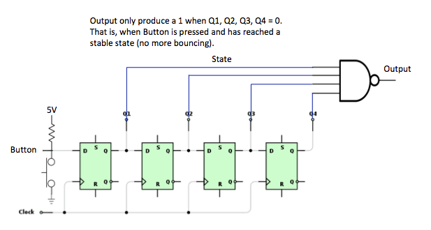
The button state is clocked in to the d flip-flops, and only when all the flip-flops have registered the same state the output will change. This solution is typically found in programmable logic, but it is rather expensive to realise by using discrete components.
A really efficient and reliable debounce circuit can be built bu using a SR-latch in conjunction with a SPDT switch. In one position the switch is connected to the set input, while the other position of the switch is connected to reset input of the latch. That way you do not have to consider the time you expect the bouncing to last, or the duration between each of the spurious voltage pulses.
Software debounce methods
If a software debounce solution is desired, one possibility is to check the button state twice, within a short time windows. I.e. check, delay, check again. The following source code listing illustrates one possibility:
Note that the variables are declared static inside the loop() function. This ensures that the value is persistent between the invocation of the function. Alternatively they could be declared globally, i.e. outside of any function definition.
 1#include <Arduino.h>
 2
 3const uint8_t push_button_1 = 11;
 4const uint8_t greenLED = 2;
 5
 6void setup() {
 7  pinMode(push_button_1, INPUT);
 8  pinMode(greenLED, OUTPUT);
 9  Serial.begin(9600);
10}
11
12void loop() {
13
14  static uint32_t latest_edge_millis = 0;
15  static uint8_t previous_button_state = LOW;
16  static uint8_t button_event = LOW;
17  static uint16_t counter = 0;
18
19  uint8_t button_state = digitalRead(push_button_1);
20
21  if(button_state != previous_button_state){
22    if(button_state == HIGH){
23      Serial.print("Rising edge.");
24      Serial.println(counter);
25      counter++;
26
27      latest_edge_millis = millis();
28      button_event = HIGH;
29    }
30    previous_button_state = button_state;
31  }
32
33  if(millis() > latest_edge_millis + 100 && (button_event == HIGH)){
34    Serial.println("Button event detected");
35    button_event = LOW;
36  }
37}
Switch debounce for the edge detection demo
The following code listing demonstrates one way to solve the bouncing problem from the example in the section Bounce problem edge detection demonstration.
 1#include <Arduino.h>
 2
 3const uint8_t btn1 = 5;
 4const uint8_t debounce_interval = 10;
 5uint32_t btn1_change_timestamp = 0;
 6/**
 7 * Default the btn1_prev_state to 1 if using pull up resistors, and a push
 8 * button which pulls the logic level low. Change to 0 if using pull down
 9 * resistors.
10 *
11 * Othervise the MCU will detect a single button event upon boot.
12 *
13 * Also remember that the rising edge will be at button release, if you are
14 * using pull up resistors.
15 */
16uint8_t btn1_prev_state = 1;
17uint8_t btn1_dbn_state = 1;
18
19uint8_t rise_edge_cnt = 0;
20uint8_t fall_edge_cnt = 0;
21
22void setup() {
23  pinMode(btn1, INPUT);
24
25  Serial.begin(9600);
26}
27
28
29void loop() {
30
31  /**
32   * Send a message on the serial port on each rising, and falling
33   * edge of the push button
34   */
35
36  uint8_t btn1_state = digitalRead(btn1);
37
38  // Check if the button state has changed compared to the previos time we checked
39  if(btn1_state != btn1_prev_state){
40
41    // Store a timestamp of the last time the button state changed
42    btn1_change_timestamp = millis();
43
44    btn1_prev_state = btn1_state;
45  }
46
47  // Make sure the button state remains stable for a time equal to debounce_interval
48  if((millis() - btn1_change_timestamp) > debounce_interval){
49
50    // Check if the button state has changed compared to the previous time it was debounced
51    if(btn1_state != btn1_dbn_state){
52      if(HIGH == btn1_state){
53        Serial.print("Rising edges detected: ");
54        Serial.println(++rise_edge_cnt);
55      }
56      if(LOW == btn1_state){
57        Serial.print("Falling edges detected: ");
58        Serial.println(++fall_edge_cnt);
59      }
60      btn1_dbn_state = btn1_state;
61    }
62  }
63}
Exercise: Push button de-bouncing
In this exercise you will (hopefully) experience the bouncing problem in practice, and then resolve the problem by applying the technique discussed in the previous section.
Write a program which toggles a LED on the rising edge of a push button. The program should also print a message to the serial port on the rising edge.
Extend the program with the code required to avoid bouncing problems.
Try to press the push button repetitively to make sure that it is not bouncing.
Exercise: Stopwatch
Since we now know some ways of eliminating the glitches (or jitter) on the button, we can design a nice stopwatch timer, where a push button starts and stops the timing. Use the comments in the source code as your guide on how to solve this exercise.
 1#include <Arduino.h>
 2
 3// include Arduino.h library
 4// define led_pin attached to pin 2
 5// define button_pin attached to pin 10
 6
 7void setup() {
 8  // set button_pin as input
 9  // set led_pin as output
10  // start serial in 9600 hertz
11  // turn off LED
12  // notification on serial: "Setup ready"
13}
14
15void loop() {
16  // define static 8-bit integer button_past
17  // define 8-bit integer button_now
18  // define static 8-bit integer timer_active
19  // define static 32-bit integer start_time
20  // define static 8-bit integer stop_past
21  // define 32-bit integer delta_time and set initial value as 0
22  // define float timer_seconds and set initial value as 0
23  // set button_now from digital pin button_pin
24  //if((button_now equals to 0) and (button_past == equals to 1)){
25    //if timer_active equals to 0{
26      // start_time as milliseconds
27      Serial.print("Starttid: ");
28      // print start_time
29      // set timer_active to 1
30      }
31    else{
32      // stop_time as milliseconds
33      Serial.print("Stopptid: ");
34      // print stop_time
35      // calculate delta_time
36      Serial.print("Delta tid: ");
37      // print delta_time
38      // convert delta_time into seconds as "timer_seconds"
39      Serial.print("Delta tid sekunder: ");
40      // print timer_seconds
41      // set timer_active to 0
42    }
43  }
44
45  button_past = button_now;
46  delay(1);
47}
Todo
Add solution proposal after the lecture
Note
Note that this is not necessarily a perfect solution. If you press and release the button so fast that the program cannot catch digitalRead(button_pin) line - since the microcontroller reads memory line by line - then you miss a button press. This will likely not be a problem for manual push buttons (unless your microcontroller executes a lot of code between each time it reads the digital input), but it might be a problem if you try to use the stopwatch for timing of something which is faster than a human hand. E.g. if you want to determine the speed of you bicycle, and try to measure the interval between pulses from a sensor on the wheel. The solution for fast signals is to use the interrupt system. This will be covered in a future lecture.
Rough Timing in Arduino
The Arduino functions associated with timing are: