Digital I/O, and serial port output
In this lesson we will cover how to deal with digital inputs, digital outputs, as well as how to send data out through the serial port.
In addition to the microcontroller topics, we also need to cover some general programming concepts.
The digital inputs and outputs (digital I/O) on the Arduino are what allow you to connect sensors, actuators, and other ICs to the Arduino . Learning how to use the inputs and outputs will allow you to use the Arduino to do some really useful things, such as reading switch inputs, lighting indicators, and controlling relay outputs.
Arduino program structure
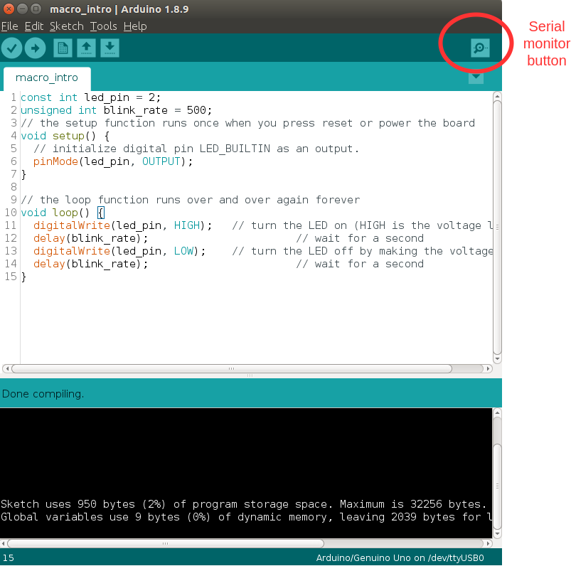
You remember that in the last course we have compiled the built-in Blink example. Let’s remember the procedure first:
// the setup function runs once when you press reset or power the board
void setup() {
   // initialize digital pin LED_BUILTIN as an output.
   pinMode(LED_BUILTIN, OUTPUT);
}

// the loop function runs over and over again forever
void loop() {
   digitalWrite(LED_BUILTIN, HIGH);   // turn the LED on (HIGH is the voltage level)
   delay(1000);                       // wait for a second
   digitalWrite(LED_BUILTIN, LOW);    // turn the LED off by making the voltage LOW
   delay(1000);                       // wait for a second
}
Lets start by breaking down the different parts of the code.
First you should know that any text which is preceded by two forward slashes // is considered a comment, and is ignored. This is one of the two most common ways to add comments to you code, and is a very useful and important part of programming. Document anything which is not obvious in the code.
The first lines of code is the setup() function. A function is a group of code under a identifier (the identifier setup()). The body of the setup() function is delimited by the curly brackets {, and }. In this function the only statement we see is a call to another function, the pinMode(LED_BUILTIN, OUTPUT); function. This function configures the pin which is connected to the build in LED as a output. It is one of the many functions in the Arduino library.
void setup() {
   // initialize digital pin LED_BUILTIN as an output.
   pinMode(LED_BUILTIN, OUTPUT);
}
Further down we see another function definition loop(). When the processor has finished executing alle the statements in the loop() function, it starts over again from the top. Thus the microcontroller is able to continuously perform its duties. The first statement in the loop() function is a call to the function digitalWrite(LED_BUILTIN, HIGH);. The function tells the microcontroller to set the pin connected to the built in LED high, i.e. the microcontroller will output 5 V on this pin. The second statement delay(1000); performs a delay of 1000 milliseconds, i.e. 1 second. The microcontroller sits on this position in the code for one second, performing no other task except waiting. We then see a instruction to turn the output low digitalWrite(LED_BUILTIN, LOW);, followed by another delay.
// the loop function runs over and over again forever
void loop() {
   digitalWrite(LED_BUILTIN, HIGH);   // turn the LED on (HIGH is the voltage level)
   delay(1000);                       // wait for a second
   digitalWrite(LED_BUILTIN, LOW);    // turn the LED off by making the voltage LOW
   delay(1000);                       // wait for a second
}
Perhaps the need for two delay functions confuses you, i.e. why can we not use a single delay with the parameter 2000. try to think about what would happen if we only had a single delay in the code. Say we removed the second delay function, we would get the following structure of our program:
digitalWrite(LED_BUILTIN, HIGH);delay(1000);digitalWrite(LED_BUILTIN, LOW);
When the program reaches line 3, it will immediately jump to line 1 (due to the fact that we are in the loop() function). Hence the output goes from LOW, to HIGH as fast as the microcontroller is able to execute the instructions. It will then remain in HIGH for one second again. In practice the LED will remain HIGH for more than 99.9% percent of the time, and will appear to be glowing constantly.
A final thing to note about this example, the code LED_BUILTIN is a Macro definition, a pre-processor directive which is stored somewhere in the Arduino libraries. In the example the term LED_BUILTIN is a place holder for the number 13. Instead, we could have written the code like the following, and literally nothing would have change in practice:
// the setup function runs once when you press reset or power the board
void setup() {
   // initialize digital pin LED_BUILTIN as an output.
   pinMode(13, OUTPUT);
}

// the loop function runs over and over again forever
void loop() {
   digitalWrite(13, HIGH);   // turn the LED on (HIGH is the voltage level)
   delay(1000);                       // wait for a second
   digitalWrite(13, LOW);    // turn the LED off by making the voltage LOW
   delay(1000);                       // wait for a second
}
However, the latter example is less flexible than the first. The reason is that whenever you have another LED attached to your Arduino, but in another pin than 13, you need to change this definition in 3 different places. Therefore programming languages typically offer different kinds of place holder mechanisms. Macro definitions is one way to introduce them in C/C++, and is defined like:
#define identifier replacement
Such as:
#define LED_BUILTIN 13
Basically, it says your processor that “whenever you see this identifier, replace it with the replacement”. This way of introducing a place holder is executed in a pre-processor directive. It is not different than deleting one text (as identifier) and replacing it with another text (as replacement). All these replacements are performed before the compiler starts the job of interpreting our code.
In fact any statement which begins with # is interpreted by the preprocessor. In addition to #define, you should also know about #include, which imports another file in to your source file.
Exercise: define a macro
Let’s define our own macro definition for our external LED, attached to pin number 2. Also, change the blink rate from 1000 milliseconds to half a second.
 1#define MY_EXT_LED 2
 2#define BLINK_RATE 500
 3// the setup function runs once when you press reset or power the board
 4void setup() {
 5  // initialize digital pin LED_BUILTIN as an output.
 6  pinMode(MY_EXT_LED, OUTPUT);
 7}
 8
 9// the loop function runs over and over again forever
10void loop() {
11  digitalWrite(MY_EXT_LED, HIGH);   // turn the LED on (HIGH is the voltage level)
12  delay(BLINK_RATE);                       // wait for a second
13  digitalWrite(MY_EXT_LED, LOW);    // turn the LED off by making the voltage LOW
14  delay(BLINK_RATE);                       // wait for a second
15}
Variable Types
Macros are a powerful tool for managing large software projects, and this will become clear as the course progresses. For constant parameter values however it is not necessarily true that a #define statement is the best choice. In any case a #define statement is only suitable for values which are constant at run-time. I.e. macros can be complex and auto-generate code at compile-time, but when the program is running on your microcontroller, they have all been replaced with the value the preprocessor determined that they should have.
For dynamic values (values which can change while the microcontroller is running), we use variables. A variable is closely related to the variable you know from mathematics. It is some identifier, which is associated with some value. For example the following code would first declare a variable with a size of 8 bit, and give it a value of 23. Then later on the value is changed to 42.
uint8_t number_of_students = 23;

number_of_students = 42;
The declaration of the variable is only performed the first time the identifier is introduced. It tells the compiler how much memory should be made available for the value, and what type of value we intend to store. uint8_t means unsigned 8-bit integer. I.e. a unsigned number which can not contain fractional parts, and with a range of values from 0 to 255. We use the equal sign = to assign a value to the identifier. Attempting to assign something which is outside the values supported by the declaration is an error.
The following list provides a overview of the default variable types supported in the Arduino framework. You should note that uint8_t is not part of the list. This is because the name uint8_t, and many others like it (e.g. int32_t) are just redefinitions of the standard names to make them more readable. Unlike the standard names, names like uint8_t makes it immediately obvious what kind of type we are dealing with.
Numeric types |
Bytes |
Range |
Use |
|---|---|---|---|
int |
2 |
-32768 to 32767 |
Represents positive and negative integer values. |
unsigned int |
2 |
0 to 65535 |
Represents only positive values; otherwise, similar to int. |
long |
4 |
-2147483648 to 2147483647 |
Represents a very large range of positive and negative values. |
unsigned long |
4 |
0 to 4294967295 |
Represents a very large range of positive values. |
float |
4 |
3.4028235E+38 to -3.4028235E+38 |
Represents numbers with fractions; use to approximate real-world measurements. |
double |
4 |
The same as float |
In Arduino, double is just another name for float. |
boolean |
1 |
false (0) or true (1) |
Represents true and false values. |
char |
1 |
-128 to 127 |
Represents a single character. Can also represent a signed value between -128 and 127. |
byte |
1 |
0 to 255 |
Similar to char, but for unsigned values. |
string |
Represents arrays of chars (characters) typically used to contain text. |
void |
Used in function declarations where no value is returned, or for pointer to unspecified type. |
Variables are generally defined such that the values can be changed during the execution of the program; after some calculations, in conditional cases, as a sensor readings change etc. On the other hand, there are some situations where the value is not expected to change. Through the whole program life time, it will remain the same value. In these cases it is more efficient and safe to define them as constant values, which tells the compiler that this value has just read-only property. This feature is useful for especially longer codes in their debug process. In our case, we know that the LED is always connected a predefined pin and it will not be changed in any conditions. Constant “variables” have some advantages over #define, we will not go in to the details here, but both of them are used extensively.
The following example uses a const “variable” for the pin definition, and a regular variable for the blink rate. Please note that it is optional to add the const qualifier. It improves safety, when you as the developer intends for the value to never change. In some other application it might be needed to change the led pin while the program is running, and if that is the case you can not use const.
 1const int led_pin = 2;
 2unsigned int blink_rate = 500;
 3// the setup function runs once when you press reset or power the board
 4void setup() {
 5  // initialize digital pin LED_BUILTIN as an output.
 6  pinMode(led_pin, OUTPUT);
 7}
 8
 9// the loop function runs over and over again forever
10void loop() {
11  digitalWrite(led_pin, HIGH);   // turn the LED on (HIGH is the voltage level)
12  delay(blink_rate);                       // wait for a second
13  digitalWrite(led_pin, LOW);    // turn the LED off by making the voltage LOW
14  delay(blink_rate);                       // wait for a second
15}
See also
Since in the embedded world memory usage is often a major concern, it is good to have a more friendly type definitions. Instead of trying to remember the memory spaces of all the variable types: uint8_t, uint16_t, uint32_t.
For example char is int8_t but byte is uint8_t.
Atmega328 GPIO pins
Most of the physical pins on the microcontroller in the Arduino UNO (The Atmega328) are general purpose input output (GPIO) pins. This means that they support both the reading of input signals, and writing of output signals. All the GPIO pins support digital input, and digital output. In addition to digital I/O they also support various extra features such as analog input, pulse width modulation, UART, etc. The extra features that are supported, will vary from one pin to the next.
The following figure depicts the internal structure of a single GPIO pin:
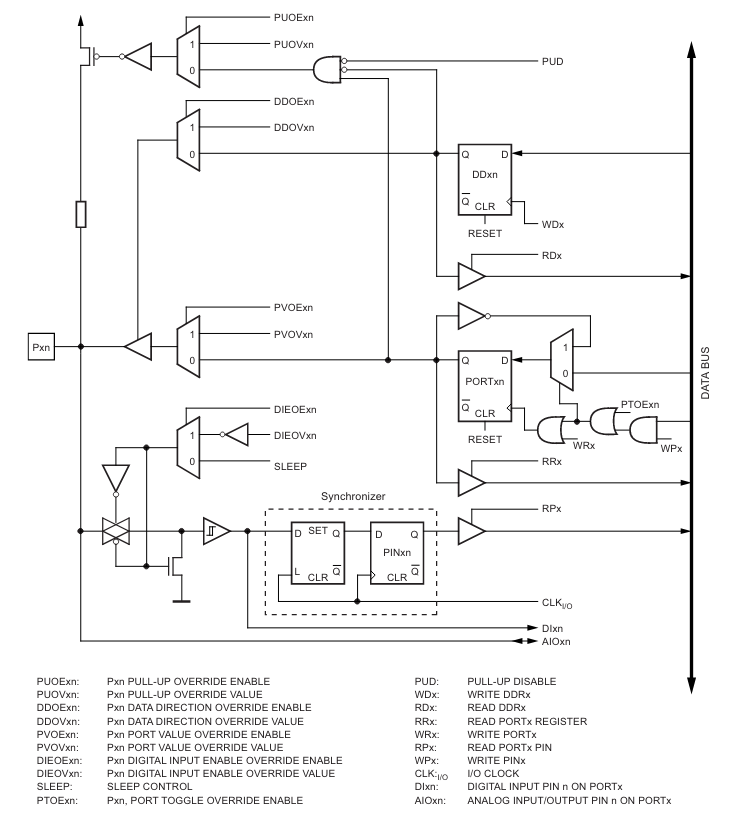
We will not go in to details about the internal operation here, but you should know that it is the configuration of this digital circuit that change when you call the function pinMode(MY_EXT_LED, OUTPUT);, or pinMode(MY_EXT_LED, INPUT);
Digital outputs
Digital outputs have already been demonstrated thoroughly. There are however some general things to note about the operation of the digital outputs.
The maximum input or output current of any one pin is 20 mA. The output uses a transistor pair in a push-pull structure. It is able to raise the pin up to 5 V, or to pull it down to GND (0 V). The pin can either sink, or source current. I.e. the direct current can flow out of the microcontroller, or it can flow in to the microcontroller.
Selecting a suitable current limiting resistor for the LED
As you probably noticed, when we are controlling a LED from the Arduino we are using a resistor in series with the LED. This resistor is required in order to not destroy the LED, and should be of an appropriate resistance.
The characteristics of a LED (like any diode) is inherently non-linear. A small voltage variation may cause a large variation in current through the diode. If this is not managed the diode will be destroyed by excessive current. As the light intensity of the diode depends on current, it is apparent that the diode should be supplied by a current source. A high performance current source is a complex device however, and thus we often opt to approximate the current source by means of a resistor.
The color of a LED is not determined by the color of the package, but rather by it’s internal physical structure. The different colors thus have different characteristics, such as different nominal voltage drop. This has implications on the selection of the resistor. Also the value of the selected resistor will impact the light intensity of the LED. The minimum resistor value (i.e. maximum light intensity) depends on the maximum current, as well as the voltage/current-characteristics of the LED.
The digital outputs of the Arduino UNO has a high voltage level of 5 V. The voltage drop of a LED will typically vary between 1.8 V and 3.3 V, depending on the color. It will also vary slightly depending on the current, but this variation may be ignored in most applications. The maximum current of the large THT LED’s in the Arduino kit is 20 mA. By subtracting the LED voltage from the supplied voltage, we find the required voltage drop of the resistor.
The current through a resistor is given by:
Thus a approximately constant voltage drop will cause a approximately constant current. The required resistor size is thus given by:
Worst case, if the voltage drop is only 1.8V, and the maximum current is 20 mA, we get the following minimum resistor value:
In practice you might want to limit the current to a maximum of 15 mA or even less though. It the Arduino kit the recommended resistor size is 220 Ohm, which should be safe in all cases involving 20 mA LED’s. In practice values as high as 1k (or even more) may also be used, if the required light intensity is not to high.
For high power LED’s you should also make sure that the power dissipated in the resistor does nod exceed the ratings of the resistor 1.
Footnotes
- 1
For very high power applications a simple current limiting resistor is not suitable, and you should instead use power electronics. This however is a entire field of engineering on it’s own, and way outside the scope of what we will be covering here.
Digital inputs
Digital inputs will be dealt with in greater detail in a lecture specifically dedicated to it. For now we will only introduce the basics, in order to get you quickly up and running with some interesting projects.
As the name implies, digital inputs are used for getting information from the real world. A button, a digital sensor or a simple jumper cable connected to +5V (or GND) is processed in the same way in an Arduino program. So far, we have seen how to express Arduino’s feelings with digital output. Now it is time to express our desire to the Arduino. Let’s design an Arduino program to turn on/off the same LED based on a button state.
How to connect a button to the Arduino
You may think that “just to connect a button, what can it go wrong?” but unfortunately when it comes to push buttons, a common beginner mistake root from connecting the button wrong. For now, as a rule of thumb, keep in mind these two figures and check these:
|
|
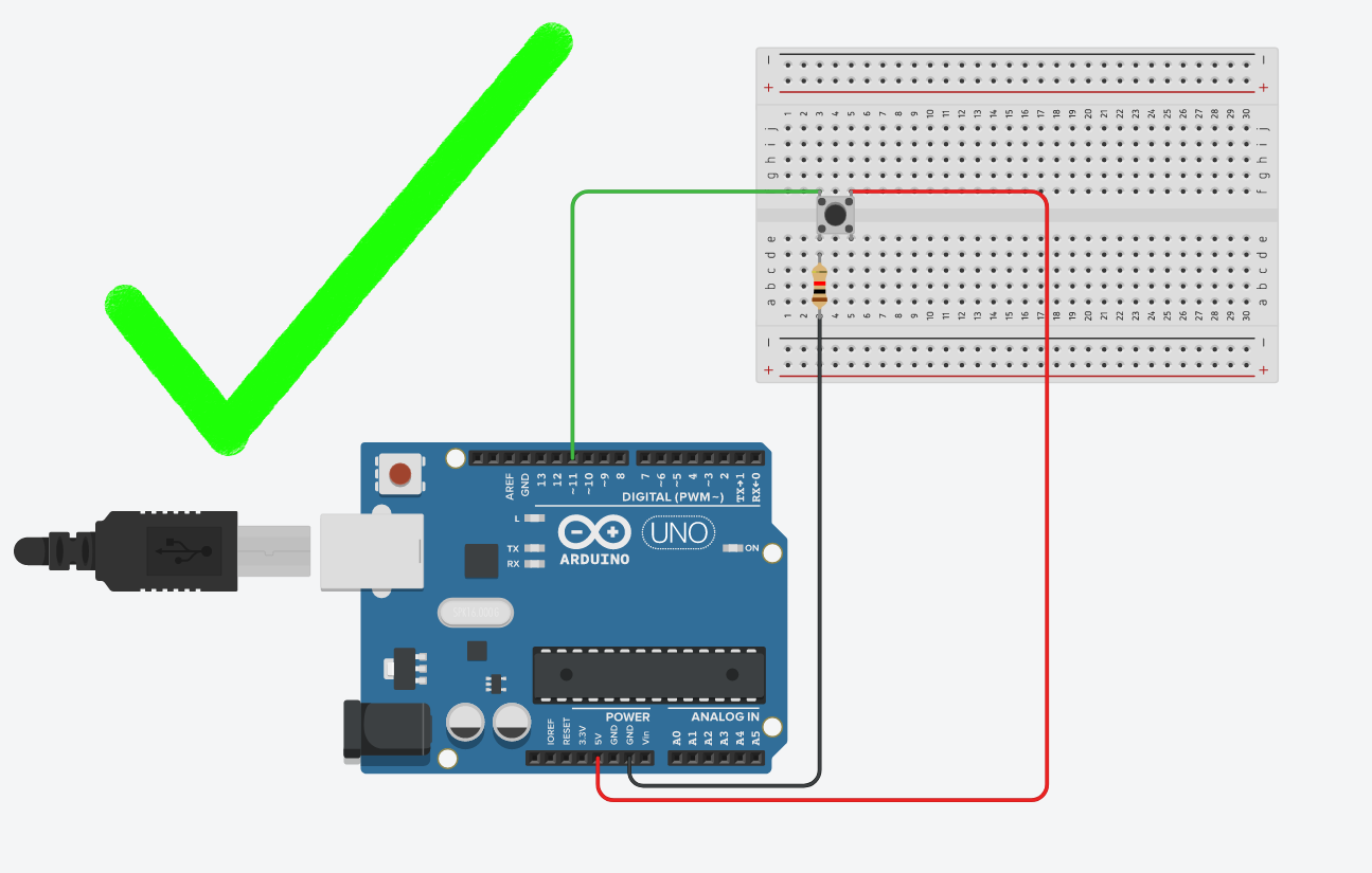
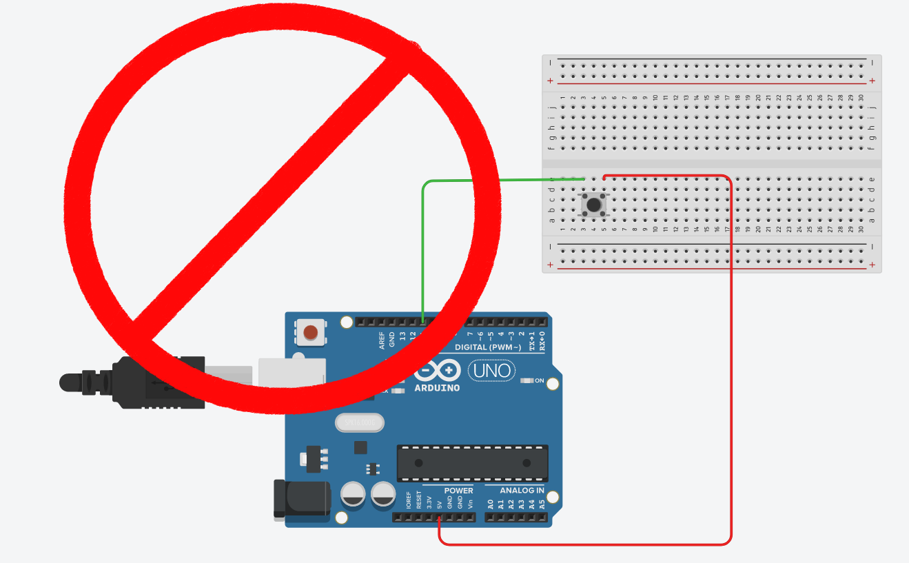
ALWAYS CHECK: - If the button orientation is correct. Remember: 1a-1b and 2a-2b are connected bus and should be place on the breadboard accordingly. - If both +5V and GND is connected. The button should have deterministic PRESSED and RELEASED voltage. Never leave a leg empty. - THE MOST CRITICAL: Are you sure that you didn’t connect +5V to GND? Always double check before connecting the Arduino to the power.
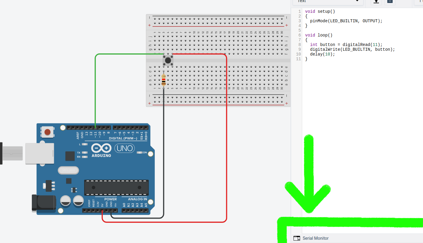
Exercise: Digital output of digital input state
The following code shows how a digital input can be used to set the state of a digital output:
void setup()
{
  pinMode(LED_BUILTIN, OUTPUT);
  pinMode(11, INPUT); // Input is the default state, but it is sometimes good to be explicit for clarity
}

void loop()
{
  int button = digitalRead(11);
  digitalWrite(LED_BUILTIN, button);
  delay(10);
}
Test the program on you own hardware
Make the necessary modifications to allow the push button to enable blinking of the LED. (Hint: only one of the
digitalWritein your blink program should depend on the state of the push button).
Todo
Add solution proposal after the lecture
Exercise: Logic operations on digital inputs
It is possible to instruct the CPU in the Atmega328 to perform logic operations on the state of the digital inputs (or for that matter any internal state, such as a variable). The following table list the basic logical operations which are supported by the compiler (and also by the CPU):
Description |
Operator |
Logical NOT |
! |
Logical AND |
&& |
Logical OR |
|| |
This can for example be used in the following manner to get the result from the AND operation on two digital inputs:
uint8_t q1 = !digitalRead(btn_1); // The inverse of the digital input state
uint8_t q2 = digitalRead(btn_1) && digitalRead(btn_2); // The AND between the two inputs
In this exercise you will try some basic logic operations on two digital inputs connected to push buttons. The result of the operation is to be displayed on a LED. The following figure depicts the connection of the push buttons, and the LED. Note that the push buttons are using “pull-down” resistors, i.e. the digital input will go high when you push the button.
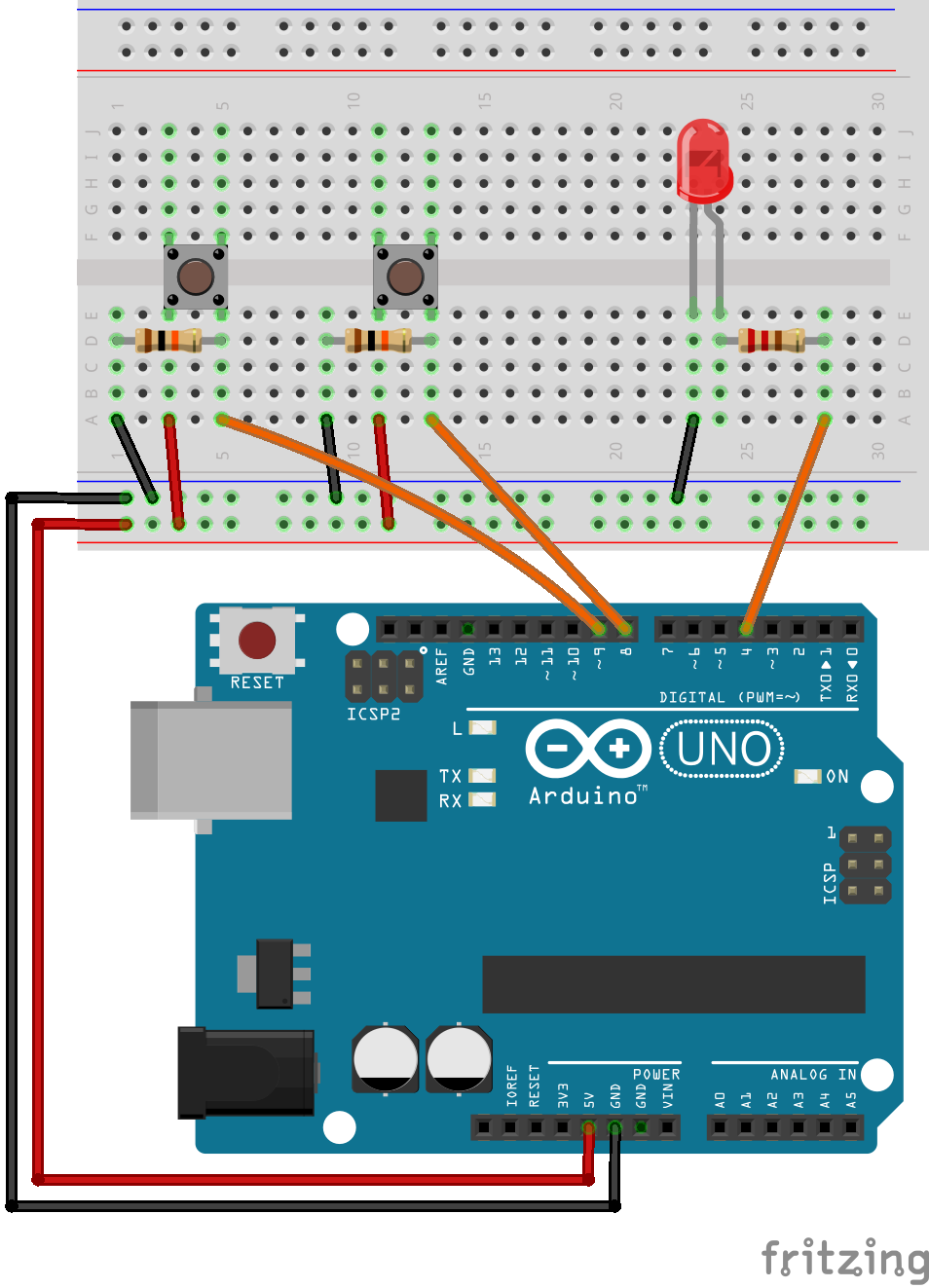
Use the following code as a basis for solving the exercise:
 1#include <Arduino.h>
 2
 3const uint8_t btn_1 = 8;
 4const uint8_t btn_2 = 9;
 5
 6const uint8_t led_1 = 4;
 7
 8void setup() {
 9  pinMode(btn_1, INPUT);
10  pinMode(btn_2, INPUT);
11  pinMode(led_1, OUTPUT);
12}
13
14void loop() {
15
16  // Use these lines if the push buttons are using "pull-up" resistors:
17  //uint8_t a = !digitalRead(btn_1); // Invert the input, as the input state is high when you are not pushing the button.
18  //uint8_t b = !digitalRead(btn_2);
19
20  // Use these lines if the push buttons are using "pull-down" resistors:
21  uint8_t a = digitalRead(btn_1);
22  uint8_t b = digitalRead(btn_2);
23
24  uint8_t q = a;
25
26  digitalWrite(led_1, q);
27
28}
Add the required code to test the NOT operation on the input from push button 1.
Add the required code to test the AND operation between the two inputs.
Add the required code to test the OR operation between the two inputs.
As you know form basics of digital electronics, these are the three fundamental logic operations. Try to build the exclusive OR using only the three basic operations.
Try to build the active high SR-latch (Hint: declare the variables
q, andq_invas global variables, i.e. declare them outside the functions).
Todo
Add solution proposal after the lecture
Serial port output
The serial port will be covered in detail in a future lecture, for now we will only be using it in its simplest form as a way to output data from the microcontroller. This will allow us some better insight in to the internal operation of the controller.
Serial port monitor in the Arduino IDE
A very useful feature which is built-in to the Arduino IDE is the serial monitor.
You can use the serial-monitor in the Arduino IDE for debugging purposes. (Of course there are many different ways of using it but personally this is by far the most common reason that I have been using it).
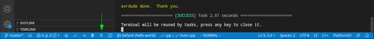
Serial port monitor in PlatformIO
PlatformIO also have a built in serial monitor. It is accessed by clicking the button looking like a power plug in at the toolbar in the bottom of the window:
Serial port monitor in TinkerCAD
TinkerCAD also have a built in serial monitor even more sophisticated than built-in Arduino serial monitor. It is located under the IDE.
Hello World
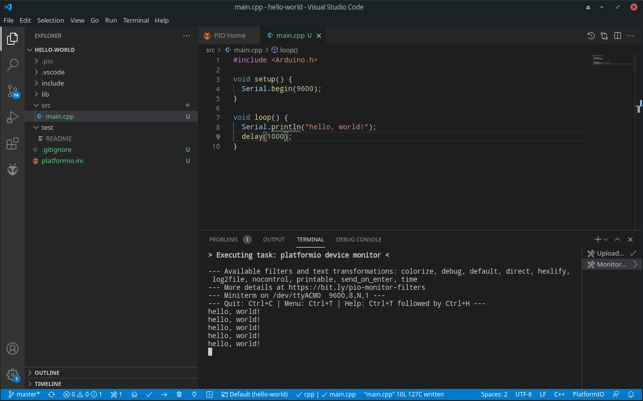
In order to write something into the serial-monitor, we need to initialize the serial communication. This is achieved by calling the method begin(9600) on the Serial object. The parameter 9600 setts the baud rate of the serial transmission, i.e. the number of symbols which is transmitted per second. For now you should leave it at the rate of 9600, in future lectures we will go in to more detail about how and when to change it. Normally the begin() method is called in the setup() function. After initialization several methods such as println() allows us to send data back from the microcontroller to our serial monitor. This is demonstrated in the following “hello, world!” example:
void setup() {
  // initialize serial communication at 9600 bits per second:
  Serial.begin(9600);
}

void loop() {
  Serial.println("hello, world!");
  delay(1000);
}
The result in PlatformIO should look something like this:
Exercise: Print some numbers
In this exercise you should expand the following program with the code necessary to print the numbers in the variables to the serial monitor.
 1#include <Arduino.h>
 2
 3uint8_t num1 = 42;
 4#define NUM2 543
 5uint8_t num3 = 899;
 6uint16_t num4 = 8973;
 7
 8int16_t num5 = -14368;
 9uint16_t num6 = -14368;
10
11float num7 = 48.9822;
12
13void setup() {
14  Serial.begin(9600);
15}
16
17void loop() {
18
19  Serial.println("The numbers are:");
20
21  // Add the println calls here:
22
23  delay(10000);
24}
Add the required calls to serial
printlnin order to print the values of all the variables. One call for each variableAre there some errors in the printout of the numbers? Try to explain why, if there is some mismatch between the numbers in the code, and the numbers showing up in the serial monitor.
Todo
Add solution proposal after the lecture
Exercise: Serial output of digital input
Inside your software, the state of a digital input is a number just like any other number. The only special property of this number is that it is always 1, or 0. Thus it can be printed on the serial port, in a similar fashion to the previous exercise.
Write a program which prints the state of two digital inputs to the serial monitor. The delay between each print should be 500 milliseconds.
Todo
Add solution proposal after the lecture
Simple arithmetics
The microcontroller (Atmega328) has built in support for some basic arithmetic operations (addition, subtraction, multiplication, but not division). Our programming language (C/C++) also support basic arithmetic operations on constant numbers or variables (including division, which is a relatively slow operation since the microcontroller does not support it directly, and has to use a multi step method to compute it).
Note that if you need slightly more advanced mathematics (e.g. square root, or logarithm), you will need to use a library which contain a function for this purpose (or alternatively you can write your own function).
We previously had a example variable for a number of students. The following example shows how you could add the number of one variable to the contents of another variable, overwriting the original value.
uint8_t number_of_students = 23;
uint8_t another_group_of_students = 19

number_of_students = number_of_students + another_group_of_students; // After this operation the value of number_of_students becomes 42
This example also illustrates an important thing to note about the assignment (=) operator. It is not a equal sign in the sense that the left and right sides have to be equal. It assigns the value which results from the expression to the right, in to the variable to the left.
Exercise: Calculator with serial port output
For each of the arithmetic operations, the output is to be printed on the serial console.
Perform the addition of 3, and 4.
Perform the subtraction of 5, and 9.
Perform the multiplication of 2, and 3.
Perform the division of 20 and 4.
Perform the division of 20 and 6.
Todo
Add solution proposal after the lecture
Exercise: Count to 10
In this exercise we will modify the hello world example to a counter, which counts to 10 over a interval of 10 seconds, before it resets back to zero. Each count value is to be displayed on the serial monitor.
void setup() {
  // initialize serial communication at 9600 bits per second:
  Serial.begin(9600);
}

void loop() {
  // Put your own code here.
  delay(1000);
}
Todo
Add solution proposal after the lecture
Exercise: Calculator with binary display
In this exercise you are going to extend the program from the exercise “Calculator with serial port output”, to one which output the result to some LEDs.
Connect 4 LEDs to some free GPIO pins.
Add the required code to control the LED in accordance with the result from the mathematical operation
Todo
Add solution proposal after the lecture
See also
The serial-monitor is basically a terminal. In order to use the serial-monitor with your board, you need to establish a UART communication link between the two. By now you should have realized that you are uploading your software to the Arduino via USB cable. This transmission is using the same protocol as you use when printing text in the serial monitor. The general name of this commonly used protocol is UART (or sometimes the more general term USART is used). It is a wide concept that requires more time to grasp the details. We will look into that in our communication protocols lesson later in the course.