Infrared (IR) communication
Optical communication
Optical comunication uses electomagnetic waves in the optical range of the electromagnetic spectrum. Normally one refers to infrared, visible, and ultrafiolet light as part of the optical spectrum. Everyting from signal lamps, and fire beacons, to the remote control of your TV uses optical communication.
Simple systems such as a fire beacon will only provide a single signal, on or off. With the help of modern electroncis it is however possible to use various forms of modulation to transfer large amounts of information using optics. This has been used by amateurs for wireless communication at 190 km (http://www.modulatedlight.org/).
In this chapter we will look at the short range wireless communication used between your remote control and your TV. A TV remote normally uses infrared light, which is why you cannot see the light. A infrared light source is placed in the controller, while a diode or transistor that is sensitive to infrared light is placed in the TV. The various manufacturers uses different modulation techniques to allow the TV to detect the different key presses on the remote. This kind of communication usually require line of sight between the sender and the receiver, although reflections from mirrors are possible.
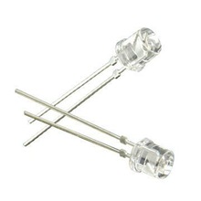
IR transmitters and receivers
Even though you cannot see the infrared light, there is still many sources of infrared light that could potentially disturb the communication link between the remote and the TV. A frequency that is relatively uncommon in the natural background noise is \(38kHz\), and thus it has been selected by many manufacturers as a carrier for the modulation.
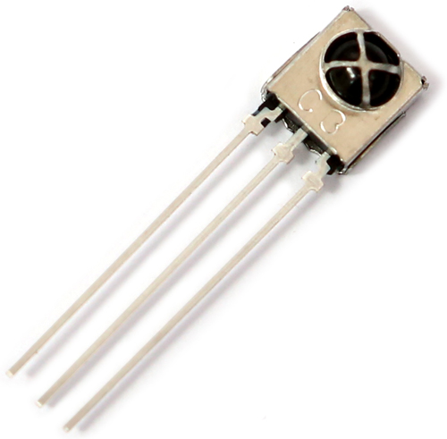
The IR receivers that are used in modern appliances are complex devices with signal conditioning to increase the reliability.
The infrared light is invisible to the human eye, but it is detectable by many digital cameras. On the camera the light will appear to be purple, as shown in the following video:
This effect may seem strange at first. The infrared light has a frequency below the frequency of red light, while purple light has frequency close to ultraviolet light.
The typical wavelength of the IR from the remote is 940 nm. At this wavelength a typical image sensor will have a response from each of the three photo diodes that is about the same (ideally the light should have been completely blocked). The equal response is misinterpreted by the digital processing system as a mixture of red and blue.
It should be noted that this is the typical behaviour, it is not exhibited by all digital image sensors. It also depends on the quiality of the IR filter in the camera.
Electrical characteristics
Phototransistor
A pure phototransistor is not ideal for detection of signals from a IR remote. The most important issue is that the voltage drop across the transistor will vary with varying intensity of the signal from the remote.
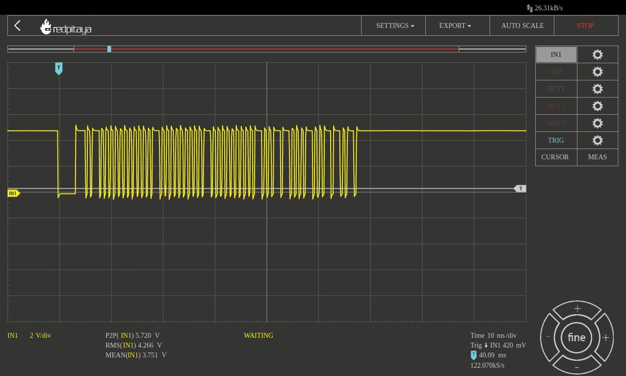
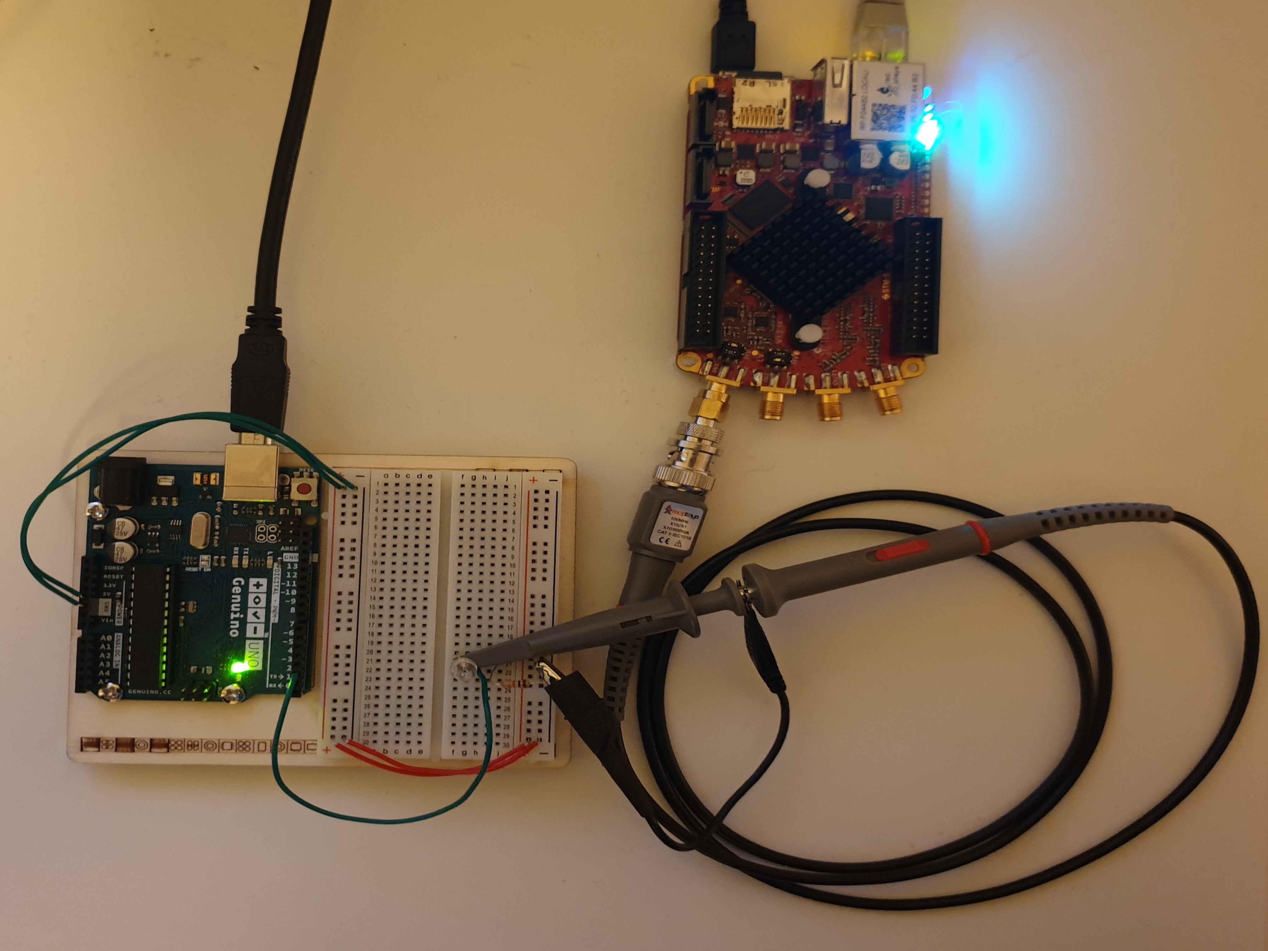
In order to test the performance of the circuit, a oscilloscope (Red pitaya) was used to measure the voltage at the emitter of the transistor:
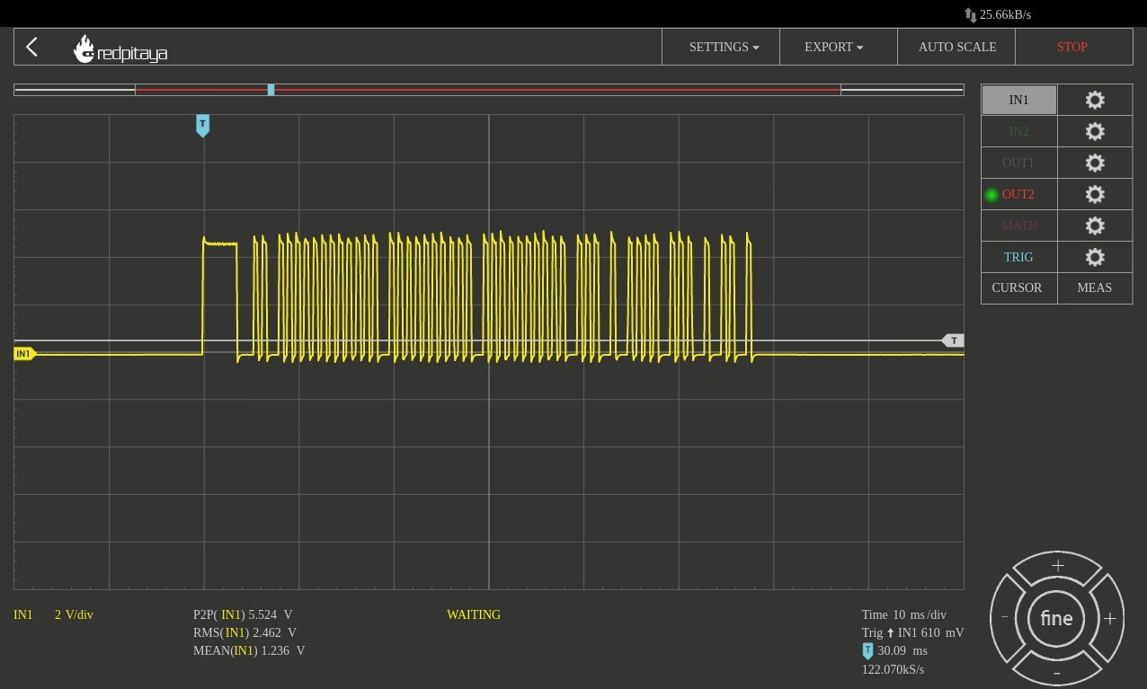
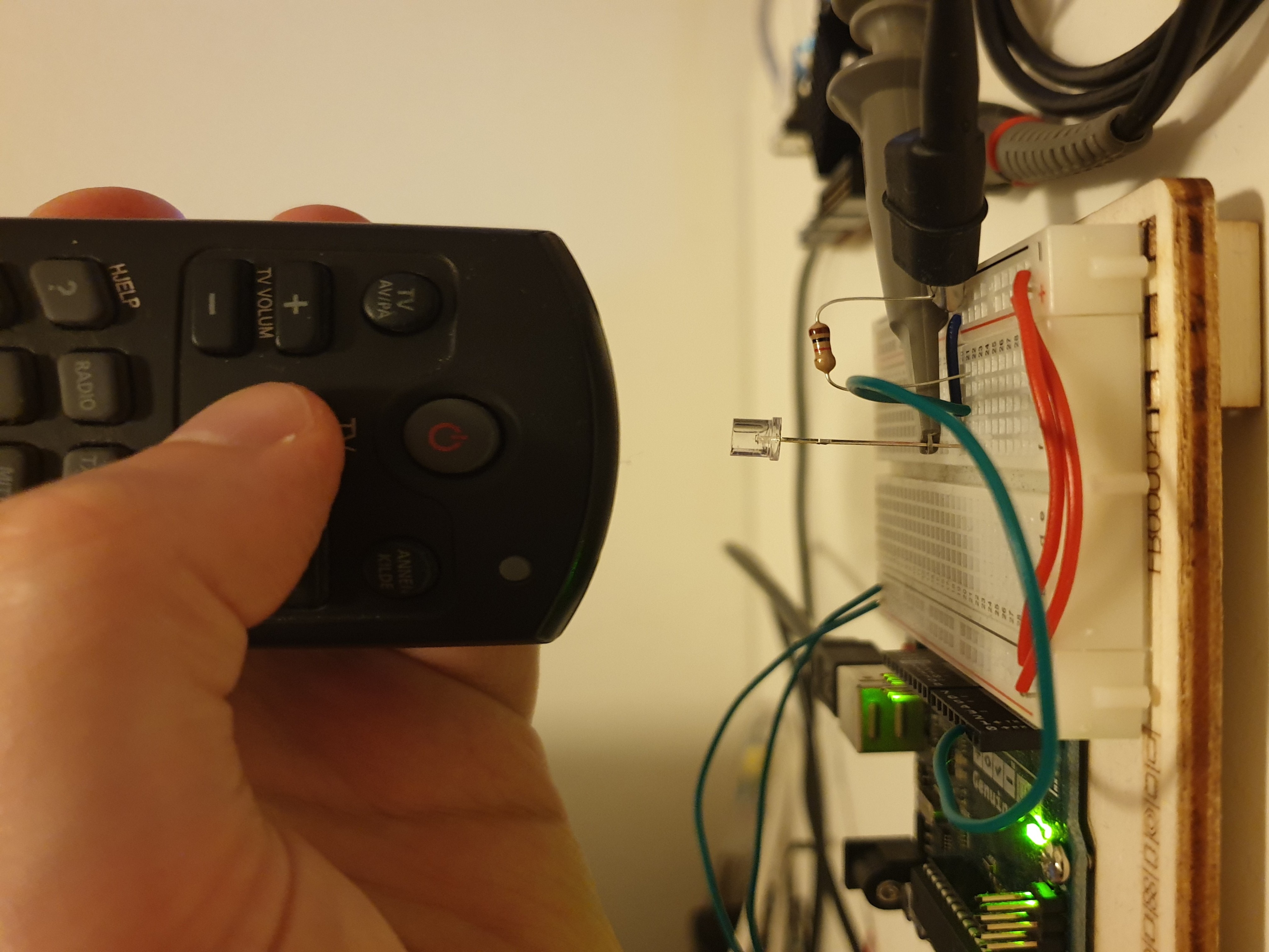
The following figure shows the output from the circuit when the IR remote is held at a distance of less than 1 cm to the phototransistor.
The quality of the signal quickly degrades as the remote is moved further away from the transistor. The following figure shows the output from the same circuit while the remote is held at a 10 cm distance.
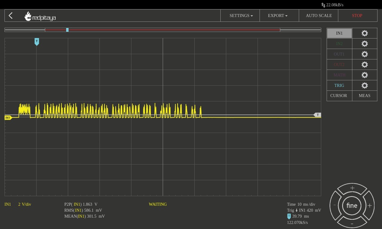
It turned out that distances of more than 1 - 2 cm degraded the quality of the signal to the point where the Arduino was no longer able to detect the remote.
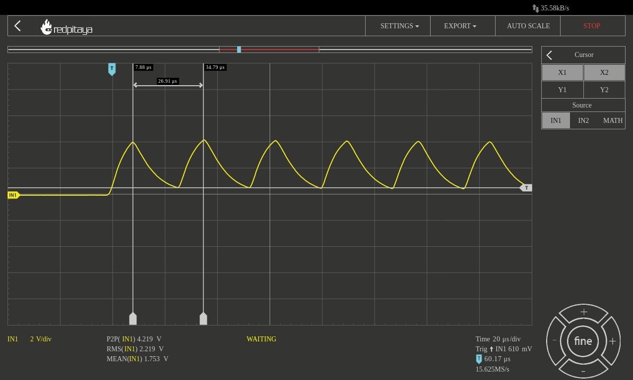
The following figure shows a close up display of the waveform from the phototransistor circuit. The wave has a (almost) sawtooth shape because of the non ideal circuit characteristics. The cursors indicate a time period \(T = 26.9 \mu s\). This corresponds to:
Demodulation of the signal
#include <Arduino.h>
#include <IRremote.h>

const uint8_t ir_input = A0;
const uint8_t ir_digital_pin = 2;

IRrecv ir(ir_digital_pin);
decode_results results;

void setup() {
  Serial.begin(9600);

  //pinMode(ir_input, INPUT);
  //pinMode(ir_digital_pin, INPUT);

  ir.enableIRIn();
  ir.blink13(true);
}

void loop() {

// uint16_t ir_data = analogRead(ir_input);

// if(ir_data > 900){
//   Serial.println(ir_data);
// }

// delay(1);


// if(digitalRead(2)){
//  Serial.println("Input");
// }

 if (ir.decode(&results)){
   Serial.println(results.value, HEX);

   switch (results.value)
   {
   case 0x122430CF:
     Serial.println("ON/OFF");
     break;
   case 0xA0441549:
     Serial.println("OK");
     break;
   case 0x122450AF:
     Serial.println("EXIT");
   default:
     break;
   }

   ir.resume();
 }

  /*
   * 122430CF - On/off button
   * AE88D06B - OK button
   * 122450AF - EXIT button
   * 122458A7 - UP arrow
   * 1224D827 - DOWN arrow
   * 69A3A44F - LEFT arrow
   * A0441549 - RIGHT arrow
   */

  //delay(1);


  int a = 10;

  int b = GetValue();

  GetValue() = 54;
  setValue(b);
 }


uint8_t& GetValue(){
  static uint8_t a = 10;

  return a;
}

void setValue(int&& value){

}