Additional material for lesson 10
Transfer function
The transfer function is very useful when analyzing the transient behavior of the motor. By using the laplace transform, we arrive at the following results for the mechanical and electrical differential equations:
A transfer function relates some input to some output. We have several possible transfer functions for the DC motor depending on the value which is of interest.
The motor speed for a given armature voltage
The motor speed for a given torque
The motor armature current for a given armature voltage
The motor armature current for a given torque
The armature current can be expressed as:
The armature angular velocity can be expressed as:
Neglecting the load torque \(T_L\) and remembering that \(k_T = k_e = k\), we can write:
We want to solve for \(\frac{\omega_m}{V_a}\), we start by isolating \(\omega_m\):
Multiplying by \(\frac{k}{k}\) in the second term we can write:
Thus the transfer function between speed and applied voltage is given by:
Similar derivations can be performed for the other transfer functions if needed.
By choosing the mechanical angular velocity and the armature current as state variables, we arrive at the following state-space representation for the motor:
It can be insightful to define and use time constants in the transfer function expressions. A mechanical time constant can be expressed as:
A electrical time constant for the armature circuit can be defined as:
Regenerative braking of the motor
It is relatively straight forward to apply control signals which converts the rotational energy of the brushed DC motor back to electrical energy. This is the most energy efficient way of breaking the motor, as the energy can be recovered and used again for another purpose. Regenerative operation on the arduino board can be problematic, as the USB power supply does not support reversed energy flow. The same is true if the supply comes from a battery which is not rechargeable. If one is pushing energy in to a DC source which does not support regenerative operation, the result will typically be that the voltage at the filtering capacitors in the DC section will increase. At some point the voltage will exceed the rating of the capacitors, and magic smoke will come out. Thus the first ting you have to do before considering regenerative operation, is to verify that the source will be able to handle it.
The trick to achieve regenerative braking it to increase the voltage coming from the motor to a level above the source voltage which was previously supplying the motor. This will allow the current direction to reverse, and thus the power flow will also be reversed. The voltage produced by the motor is proportional to the speed as well as on the magnetic field in the stator. It will always be lower than the source voltage, unless one of the following conditions are met:
For a electrically excited DC motor, if the field current is increased.
For any DC motor if some external mechanical force is driving the motor to a sufficiently high speed.
Unless you have a field winding (the small DC motor in the examples provided in this lesson does not) you will have to increase the induced voltage after it has been generated. In order to increase the motor voltage an additional external voltage converter (these are known as boost converters) could have been placed between the motor and the source, and activated when entering breaking mode. It turns out however that it is possible to exploit the internal inductance of the motor in order to increase (boost) the voltage.
If the transistors are switched correctly and at an appropriate switching frequency the only condition needed to obtain the regenerative braking is that the duty cycle of the PWM in reduced to a value below the previous steady state duty cycle. The following block diagram gives some insight in to the internal operation of the L293D:
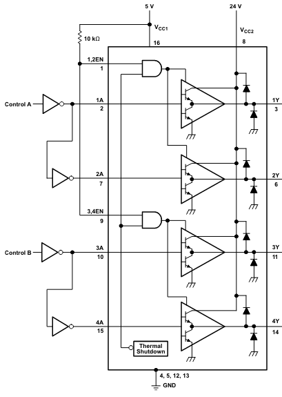
Source: The L293 datasheet
For each of the four drivers we have the following truth (function) table:
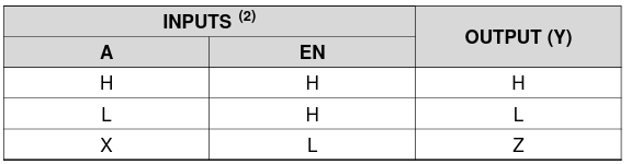
Source: The L293 datasheet
If the enable (EN) signal is low, the control signal (A) is ignored and the output goes in to a high impedance (high Z) state. When the enable signal is high, the output follows the control signal (A). By applying PWM to the enable signal and leaving the A signals fixed regenerative braking will be impossible. Whenever the output is in a high Z state, the motor current will have to circulate through the freewheeling diodes. If however the PWM signal is applied to e.g. 1A while 2A is low, a reduction in duty cycle will allow the voltage to be boosted by the motor inductance. For the opposite rotational direction the PWM signal should be applied to 2A while 1A is low.
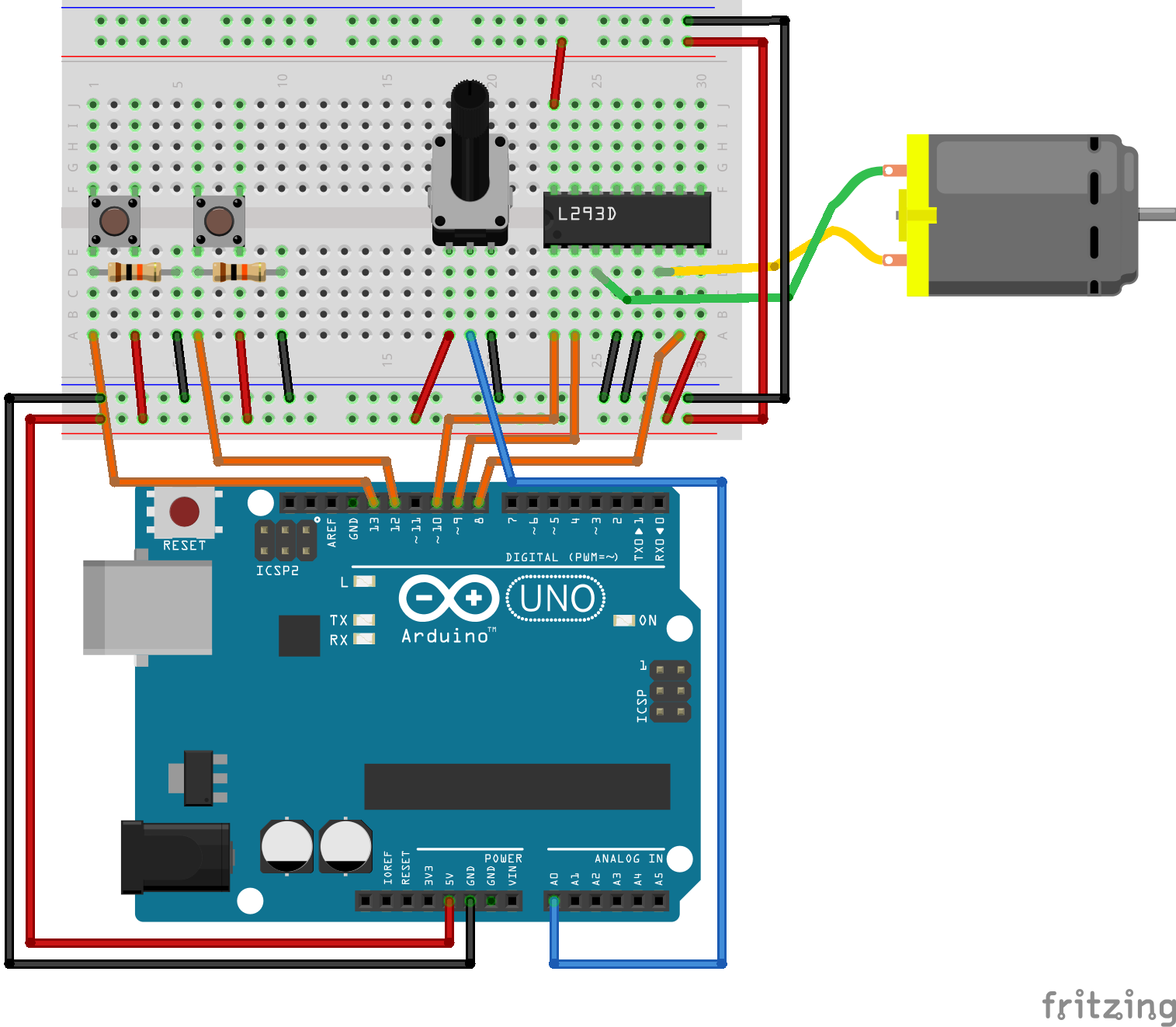
Advanced motor drive example
In the following example a potentiometer is used to control the voltage level (i.e. speed) of the motor, one push button changes rotation direction, and the other turns the drive on and off. The main idea is pretty much the same as the first program. The code is a bit more sophisticated and safer to use. The control software is built around a hierarchical State Machine, that simplifyes the management of the different states in which the motor drive may be operating. Put attention of the usage of typedef.
The following state diagram depicts the operation of the software:
![[*] --> STOPPED
STOPPED -> RUNNING : enable_button
RUNNING -> STOPPED : enable_button
STOPPED: motor_control(0, 0);
RUNNING: duty_cycle = analogRead(control_voltage)/4;
state RUNNING {
[*] --> FORWARD
FORWARD -> REVERSE : direction_button
REVERSE -> FORWARD : direction_button
FORWARD: motor_control(duty_cycle, FORWARD);
REVERSE: motor_control(duty_cycle, REVERSE);
}](../../_images/plantuml-9c16e50a39d7098f43e481dec8c0021b366459d7.png)
The following source code listing is the complete software for the motor drive:
Show/Hide Code
#include <Arduino.h>

const uint8_t enable1 = 6;
const uint8_t input1 = 5;
const uint8_t input2 = 4;
const uint8_t enable_button = 12;
const uint8_t direction_button = 11;
const uint8_t control_voltage = A0;

//#define DEBUG

typedef enum {
  FORWARD,
  REVERSE
} direction_t;

typedef enum {
    RUNNING,
    STOPPED
} motor_state_t;


void motor_control(uint8_t duty_cycle, direction_t direction);
int buttonPressed_debounce(uint8_t digital_input, uint8_t debounce_delay);


void setup(){
  pinMode(enable1, OUTPUT);
  pinMode(input1, OUTPUT);
  pinMode(input2, OUTPUT);

  pinMode(enable_button, INPUT);
  pinMode(direction_button, INPUT);

  Serial.begin(9600);
}

void loop(){

  motor_state_t motor_state = STOPPED;
  direction_t motor_direction = FORWARD;
  uint8_t duty_cycle = 0;

  for(;;){

    duty_cycle = analogRead(control_voltage)/4;
    #ifdef DEBUG
    Serial.print("Duty cycle: ");
    Serial.print(duty_cycle);
    Serial.print("\n");
    delay(1000);
    #endif

    /*
     * State machine for motor control.
     */
    switch (motor_state)
    {
    case RUNNING:

      if(buttonPressed_debounce(enable_button, 50)){
        motor_state = STOPPED;
        Serial.println("Motor stopped.");
      }

      switch (motor_direction)
      {
      case FORWARD:
        if(buttonPressed_debounce(direction_button, 50)){
          motor_direction = REVERSE;
          Serial.println("Motor direction reversed.");
        }

        motor_control(duty_cycle, FORWARD);

        break;
      case REVERSE:
        if(buttonPressed_debounce(direction_button, 50)){
          motor_direction = FORWARD;
          Serial.println("Motor direction forward.");
        }

        motor_control(duty_cycle, REVERSE);

        break;
      default:
        motor_state = STOPPED;
        break;
      }
      break;

    case STOPPED:
      if(buttonPressed_debounce(enable_button, 50)){
        motor_state = RUNNING;
        Serial.println("Motor enabled.");
      }

      motor_control(0, REVERSE);

      break;
    default:
      motor_state = STOPPED;
      break;
    }
  }
}

void motor_control(uint8_t duty_cycle, direction_t direction){

  if(direction == FORWARD){
    digitalWrite(input1, HIGH);
    digitalWrite(input2, LOW);
  }
  else {
    digitalWrite(input1, LOW);
    digitalWrite(input2, HIGH);
  }

  analogWrite(enable1, duty_cycle);
}

/*
 * Check if button is pressed, i.e. if it is high, and it was low before.
 * This version includes a debounce timer.
 *
 * The debounce time is stored as an array of 16 32-bit integers, thus it is
 * not very memory efficient.
 */
int buttonPressed_debounce(uint8_t digital_input, uint8_t debounce_delay) {

  static uint16_t lastStates = 0; // Store the states of digital input 0 - 15.
  static uint32_t lastEdgeDetect[16] = {0}; // Store the time of the last rising edge.

  uint8_t state = digitalRead(digital_input);


  // Check if the state of the digital input has changed.
  if (state != ((lastStates >> digital_input) & 1)) {
    lastEdgeDetect[digital_input] = millis();
  }

  if((millis() - lastEdgeDetect[digital_input]) > debounce_delay){

    lastStates ^= 1 << digital_input; // Store the current state of the digital input.

    return state == HIGH;
  }
  return false;
}
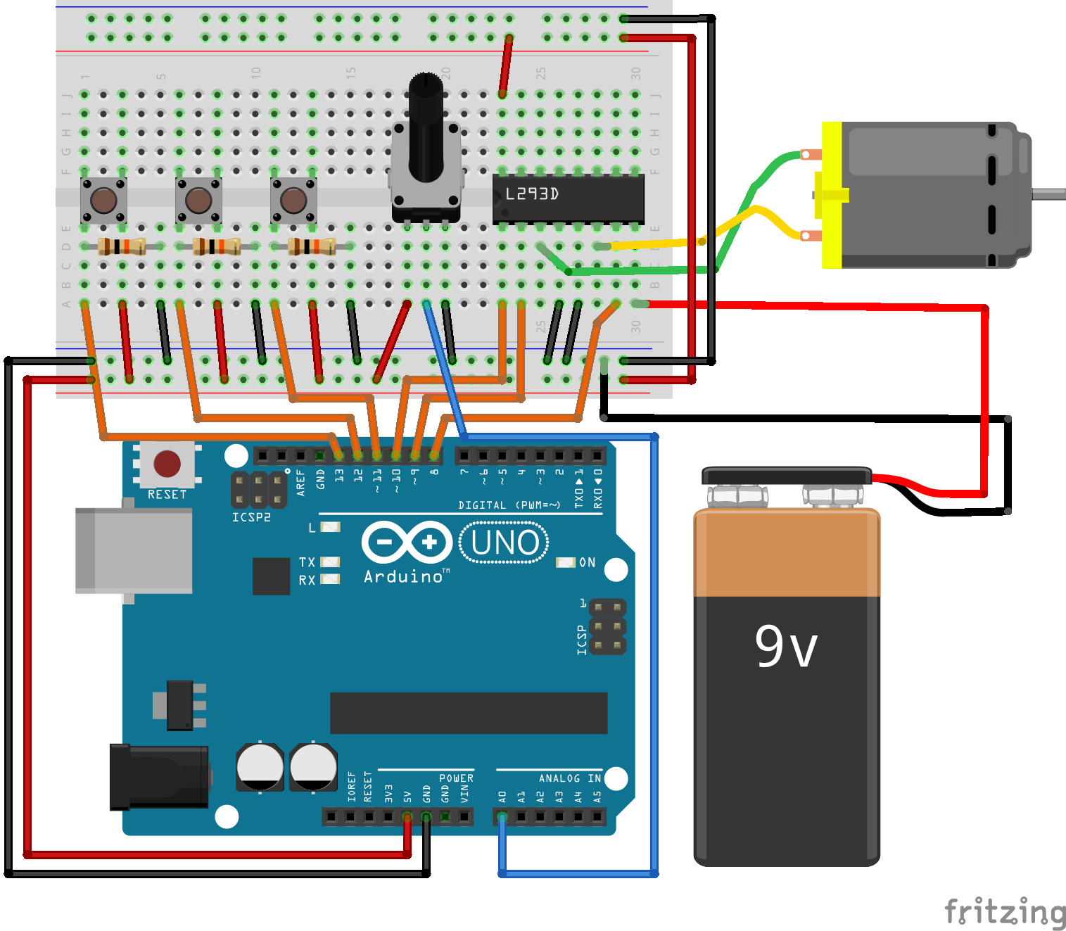
Motor drive assignment
The following circuit is the one used in assignment 5.
The following state diagram depicts the intended operation of the motor drive in the assignment:
![STATE NORMAL {
[*] --> STOPPED
STOPPED -> ACCELERATING : start_stop_button
ACCELERATING -> RUNNING : setpoint_reached
ACCELERATING -> BREAKING : start_stop_button
RUNNING -> BREAKING : start_stop_button
BREAKING -> STOPPED : zero_reached
BREAKING -> ACCELERATING : start_stop_button
STOPPED: motor_control(0, 0);
}
[*] --> NORMAL
NORMAL -> EMERGENCY_STOP : emergency_stop_button
EMERGENCY_STOP -> NORMAL : start_stop_button
EMERGENCY_STOP : motor_control(0, 0);](../../_images/plantuml-1b8c525a6f615e0ab932f955dd08b239fd4c370d.png)