LC-Display
A Liquid crystal display (LCD) 1 is a form of flat panel display where liquid crystals are used to modulate light in order to change the appearance of the display.
Some displays are application specific, and only support displaying certain patterns (e.g. only numbers, or only text). Others consists of a matrix of pixels, where each individual pixel is controlled independently, either on/off, in different shades, or even in color.
Operation of the Hitachi HD44780 display controller
The Hitachi HD44780 is a display controller for character displays, which includes support for ASCII, Japanese, and some additional symbols []. Many LC-displays, and vacuum fluorescent displays (VFD) controllers are compatible with the HD44780.
For simple display applications where one only needs to display text, this kind of display is a popular option. The display is available from multiple manufactures, and with varying size. I.e. with variation in the number of character which can be displayed.
Electrical interface
The electrical interface to the HD44780 compatible LC-display consists of several digital control signals, 4 or 8 wires with data, and a clock signal.
RS - Register select. Select between the data, and the command registers. When RS is low we are in command mode.
R/W - Read/write. Selects between reading and writing to the LCD controller. Reading is often not used, and the pin is simply tied low (to ground) for write mode.
EN - Enable. The enable signal is the clock signal where the controller asserts the state of the data inputs.
Bit 0 to Bin 7 is the data input pins. In 4 bit mode only bit 4 to bit 7 is in use.
Communication protocols
The communication protocol for the HD44780 compatible LC-display is relatively simple, and uses dedicated wires for switching between read and write mode, as well as for switching between command and data mode.
Arduino control of Hitachi HD44780 compatible display
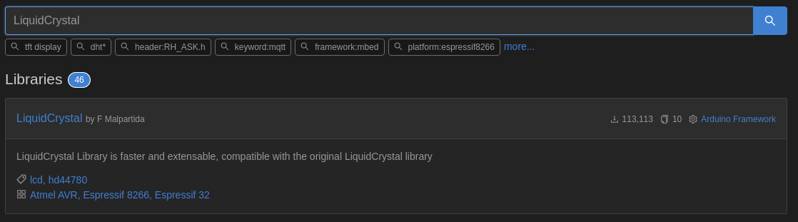
Arduino comes with a official HD44780 library, but there are several more capable libraries available. In this lesson we will be using the LiquidCrystal library by F Malpartida, which is compatible with the original Arduino LiquidCrystal library but faster and with more features.
Once the library is installed the following code will create a instance of the LiquidCrystal object called lcd. We will be using the lcd instance in the examples to follow.
const uint8_t rs = 2, en = 3, d4 = 4, d5 = 5, d6 = 6, d7 = 7;
LiquidCrystal lcd(rs, en, d4, d5, d6, d7);
Some of the LCD library methods we will be using in this lesson include:
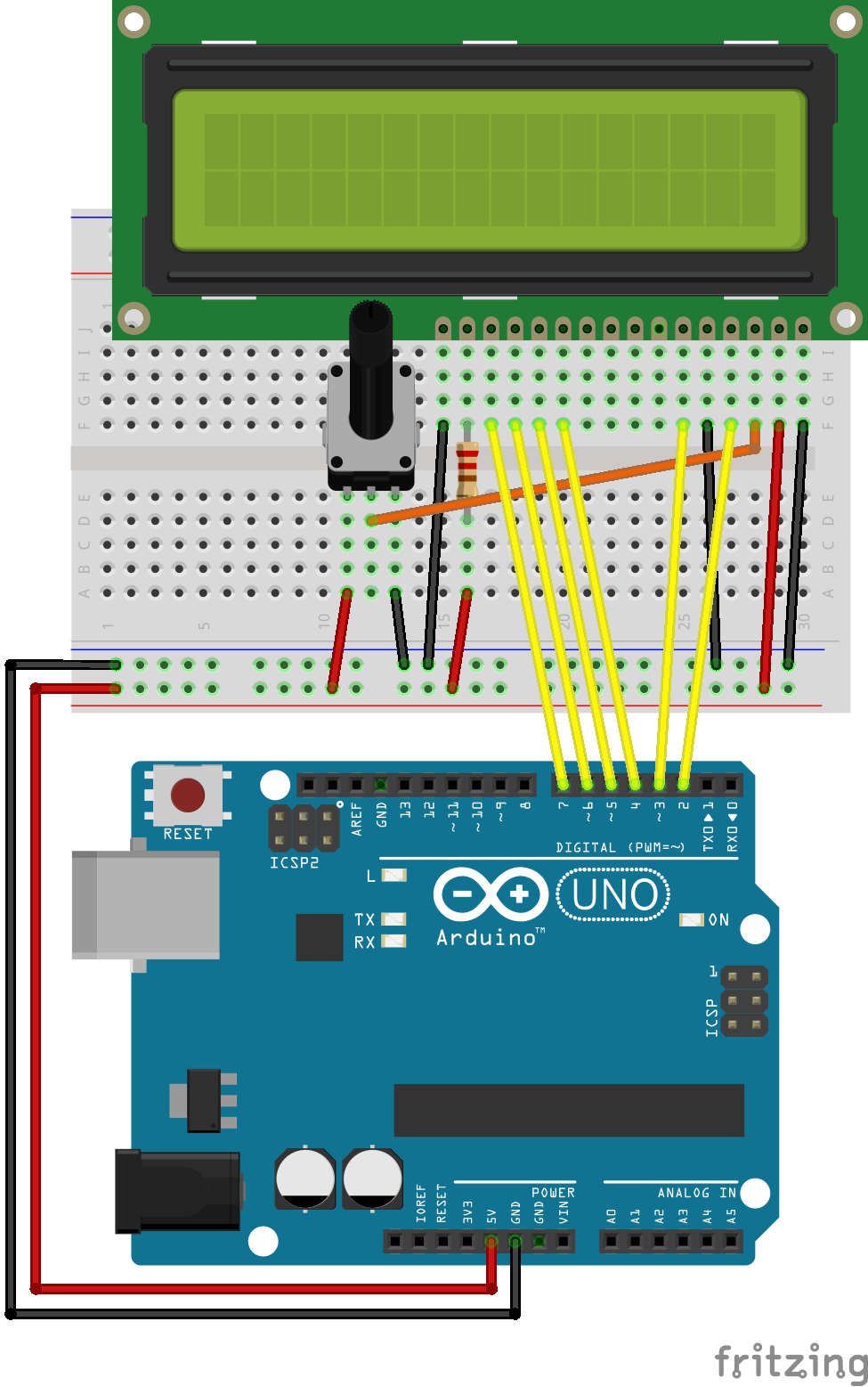
In the following examples we will be using this circuit:
Electrical test
Adjust the resistance of the potmeter until black squares are clearly visible on the top row of the LC-display. The bottom row should remain blank. Try to exceed the optimum value and observe that black squares appear in both rows, but make sure to only have squares in one row before you proceed with the firmware tests.
The backlight of the LC-display should be illuminated.
Software test
In order to verify the operation of our LC-display, a very simple firmware will be used for the initial test.
#include <Arduino.h>
#include <Wire.h>
#include <LiquidCrystal.h>

const uint8_t rs = 2, en = 3, d4 = 4, d5 = 5, d6 = 6, d7 = 7;
LiquidCrystal lcd(rs, en, d4, d5, d6, d7);

void setup() {
  // Configure the library for the number of columns and rows
  lcd.begin(16, 2);

  // Print a message to the LDC
  lcd.print("Hello, world!");
}

void loop() {
  // put your main code here, to run repeatedly:
}
The first two lines of interest provides meaningful names to some pin numbers, and instantiate the LiquidCrystal object:
const uint8_t rs = 2, en = 3, d4 = 4, d5 = 5, d6 = 6, d7 = 7;
LiquidCrystal lcd(rs, en, d4, d5, d6, d7);
Further down in the setup() function, the LCD driver is initialized and configured for a 16x2 character display by the method lcd.begin(16, 2);. Finally the method lcd.print("Hello, world!"); prints the text “Hello, world!” to the display. The cursor is automatically advanced as each character is transferred to the display.
Exercises and examples
This section contains examples on how to use the LC-display, and various exercises which allows you to practice the use of the display.
Display uptime in seconds on UART and LCD
In the following example the current uptime in seconds is displayed on the LCD, as well as on the UART. There is one important difference to note between the two, as the cursor on the LCD is moved back with the setCursor() method, while the cursor in your serial terminal is always moving forward. As you can probably realize a set cursor method for your serial monitor would be a useful addition in many cases. This is unfortunately not supported by the basic serial monitors in the Arduino IDE, or PlatformIO. It is possible to use more advanced serial monitors which supports this, but it will not be discussed in this lesson.
#include <Arduino.h>
#include <LiquidCrystal.h>

// initialize the library with the numbers of the interface pins
const uint8_t rs = 2, en = 3, d4 = 4, d5 = 5, d6 = 6, d7 = 7;
LiquidCrystal lcd(rs, en, d4, d5, d6, d7);

uint16_t seconds = 0;

void setup() {
  // Configure the library for the number of columns and rows:
  lcd.begin(16, 2);

  Serial.begin(9600);

  // Print a message to the LCD and the serial port
  lcd.print("hei, verda!");
  Serial.println(seconds);
}

void loop() {
  // Set the cursor to the first character of the second line.
  lcd.setCursor(0, 1);
  lcd.print("Tid: ");

  // Print the number of seconds since reset:
  seconds = millis() / 1000;
  lcd.print(seconds);

  Serial.print("Tid: ");
  Serial.println(seconds);

  delay(500);
}
It should be noted that since the setCursor() method only move the cursor without deleting the text on the display, it is possible that some old and irrelevant text remains in the display after you try to print some new value. For the uptime example in this section it will not be a problem since the uptime is always increasing, but consider the case where you sometimes would print a number with fewer digits than the previous number. Some of the digits in the old number would remain in the display, and the reading would thus be incorrect. There are several possible solutions to this problem, one of which is to simply clear the display before printing some new value. This is achieved by calling the method lcd.clear(); This is demonstrated in the next section.
Display voltage value from potmeter
In this example we will read a analog value from a potmeter connected to A0. The raw value, as well as the corresponding voltage level will be displayed on the LCD, as well as on the UART.
#include <Arduino.h>
#include <LiquidCrystal.h>

// initialize the library with the numbers of the interface pins
const uint8_t rs = 2, en = 3, d4 = 4, d5 = 5, d6 = 6, d7 = 7;
LiquidCrystal lcd(rs, en, d4, d5, d6, d7);

uint16_t seconds = 0;

void setup() {
  // Configure the library for the number of columns and rows:
  lcd.begin(16, 2);

  Serial.begin(9600);
}

void loop() {

  uint16_t raw_value = analogRead(A0);
  float voltage_value = raw_value/204.6; // ADC range 0 - 1023 converted to voltage range 0 - 5 V.

  // Set the cursor to the first character of the second line.
  lcd.setCursor(0, 0);

  // Note that the display will have trouble with unicode letter (å).
  // The binary value 0xc5 may be used for that character however.
  lcd.print("Råverdi: ");
  lcd.print(raw_value);

  lcd.setCursor(0, 1);
  lcd.print("Spenning: ");
  lcd.print(voltage_value);


  Serial.print("Råverdi: ");
  Serial.println(raw_value);

  Serial.print("Spenning: ");
  Serial.println(voltage_value);


  delay(500);
  lcd.clear();
}
Exercise: thermometer
In this exercise you will develop a thermometer which displays the temperature on a LC-display, as well as on the UART. You will use the TMP36 sensor which is included in the Arduino kit.
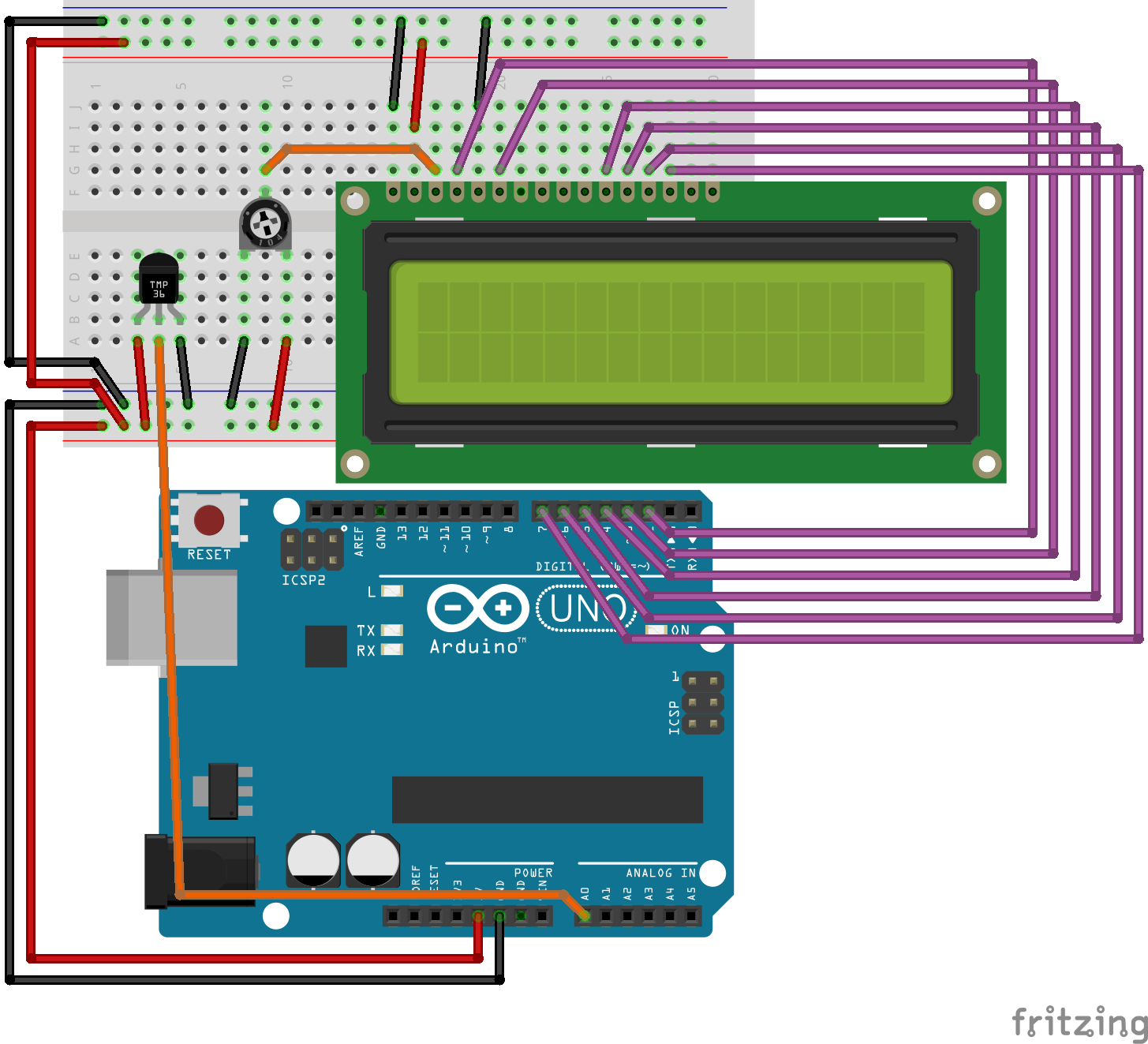
The following wiring of the LC-display and thermometer can be used. Here the LC-display is rotated 180 degrees with respect to the previous examples. This makes the orientation of the display correct with respect to the orientatin of the Arduino, but also makes the wiring more cumbersome.
Write the code required to read the temperature once every second and print the value to the UART. Use
millis()instead ofdelay().Add the code required to print the temperature on the LC-display.
Cooperate with one of your classmates, and wire up two temperature sensors to the same Arduino UNO. Print the value of both sensors simultaneously to the LC-display. One of the sensors could be used for measuring the outside temperature, while the other measures the inside temperature (as in a classical electrical temperature sensor for your home).
The temperature sensors in the Arduino kit (TMP36) are not very accurate. The datasheet states a +/- 2 degree accuracy over the specified temperature range. If this inaccuracy has a normal distribution, higher accuracy could be obtained by averaging the temperature reading over multiple samples. Write the code required to take the average over 20 samples.
Splash screen and scrolling text
Although splash screens can be anoying, and should be used sparingly, they will be used here to demonstrate some of the capabilities of the LC-display.
If you have more text to display than is available on the screen, one option is to use scrolling. Without any user input, you will have to implement automatic scrolling. You will often see this done in simple LC-displays used in various information screens.
#include <Arduino.h>
#include <LiquidCrystal.h>

// initialize the library with the numbers of the interface pins
const uint8_t rs = 2, en = 3, d4 = 4, d5 = 5, d6 = 6, d7 = 7;
LiquidCrystal lcd(rs, en, d4, d5, d6, d7);

uint32_t start_time = 0;
String testString = "Dette er ein kjempelang tekst abcdefghi.";// får plass i displayet.";

void setup() {
  // Configure the library for the number of columns and rows:
  lcd.begin(16, 2);

  Serial.begin(9600);
  start_time = millis();
}

void loop() {

  if(millis() < (start_time + 3000)){

    lcd.setCursor(0, 0);
    lcd.blink();
    lcd.print("LC-display demo");
    lcd.setCursor(0, 1);
    lcd.print("(c) HVL");
  }
  else {
    lcd.clear();
    lcd.print("123456789.");
    lcd.setCursor(0,1);
    lcd.print(testString);

    for(int i = 0; i < (testString.length() - 16); i++){
      lcd.scrollDisplayLeft();
      delay(250);
    }

    for(int i = 0; i < (testString.length() - 16); i++){
      lcd.scrollDisplayRight();
      delay(250);
    }
  }
}
Display data from UART
In this simple example we will take input from the serial terminal (UART), and print it on the LC-display. The LC-display will print both the character (if supported) and the actual binary data that is received (printed in decimal form).
Note
You should try to send special characters, such as æ, ø, and å and see how the display responds.
#include <Arduino.h>
#include <LiquidCrystal.h>

// initialize the library with the numbers of the interface pins
const uint8_t rs = 2, en = 3, d4 = 4, d5 = 5, d6 = 6, d7 = 7;
LiquidCrystal lcd(rs, en, d4, d5, d6, d7);

uint16_t seconds = 0;

void setup() {
  // Configure the library for the number of columns and rows:
  lcd.begin(16, 2);

  Serial.begin(9600);
  Serial.print("Trykk ein vilkårleg bokstav.");
}

void loop() {

  if(Serial.available()){

    uint8_t rx_data = Serial.read();
    lcd.setCursor(0, 0);
    lcd.print("Bokstav: ");
    lcd.write(rx_data);


    lcd.setCursor(0,1);
    lcd.print("ASCII kode: ");
    lcd.print("   ");
    lcd.setCursor(12,1);
    lcd.print(rx_data);
  }

  delay(500);
}
Display data in different formats
In the following examples we will be using this circuit:
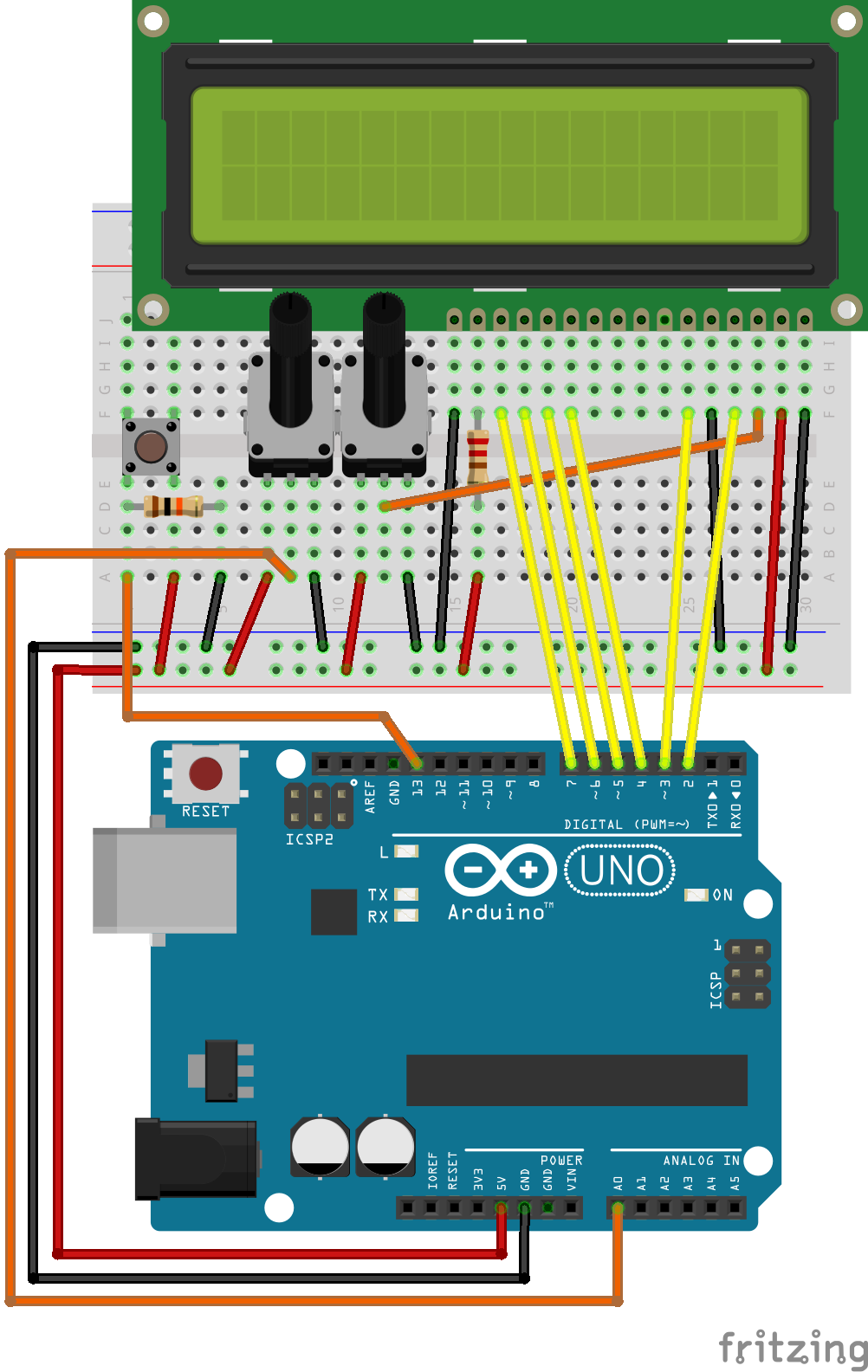
In this example we will display the raw value of the analog reading on A0. The push button on pin 13 will toggle through various number bases for the display.
#include <Arduino.h>
#include <LiquidCrystal.h>

// initialize the library with the numbers of the interface pins
const uint8_t rs = 2, en = 3, d4 = 4, d5 = 5, d6 = 6, d7 = 7;
LiquidCrystal lcd(rs, en, d4, d5, d6, d7);

const uint8_t button_pin = 13;
const uint8_t analog_pin = A0;
const uint16_t display_update_rate = 250;
uint8_t display_mode = 0;
uint8_t old_button_state = 0;
uint32_t old_time = 0;

void setup() {
  pinMode(button_pin, INPUT);

  lcd.begin(16, 2);
  Serial.begin(9600);
}

void loop() {

  uint16_t analog_raw = analogRead(analog_pin);

  // Limit the update rate of the display.
  if(millis() > (old_time + display_update_rate)){

    old_time = millis();

    lcd.clear();
    lcd.setCursor(0,0);

    if(display_mode == 0){
      lcd.print("HEX:");
      lcd.print(analog_raw,HEX);
    }
    else if(display_mode == 1){
      lcd.print("OCT:");
      lcd.print(analog_raw,OCT);
    }
    else if(display_mode == 2){
      lcd.print("BIN:");
      lcd.print(analog_raw,BIN);
    }
    else if(display_mode == 3){
      lcd.print("DEC:");
      lcd.print(analog_raw,DEC);
    }
  }

  delay(50); // Switch debounce delay (this could be done in a better way).
  uint8_t button_state = digitalRead(button_pin);

  if(old_button_state != button_state){

    old_button_state = button_state;

    if(button_state == HIGH){
      display_mode++;
      if(display_mode > 3)
        display_mode = 0;
    }
  }
}
Voltmeter with selectable scaling
The following example shows how to implement a simple state machine which allows the user to select the scaling prefix of the measured voltage.
The following state diagram depicts the operation of the prefix display toggle functionality.
![[*] --> MILLIVOLT
MILLIVOLT -down-> KILOVOLT : toggle_button
KILOVOLT -down-> VOLT : toggle_button
VOLT -> MILLIVOLT : toggle_button](../../_images/plantuml-d7a7b5f160f1bfb258d1914bf00accf950fdcc02.png)
The following source code implements the state machine, as well as the additional functionallity that is required:
#include <Arduino.h>
#include <LiquidCrystal.h>


// initialize the library with the numbers of the interface pins
const uint8_t rs = 2, en = 3, d4 = 4, d5 = 5, d6 = 6, d7 = 7;
LiquidCrystal lcd(rs, en, d4, d5, d6, d7);

uint32_t old_millis = 0;
uint32_t adc_millis = 0;

uint32_t adc_raw = 0;
float volt = 0;
float millivolt = 0;
float kilovolt = 0;

uint8_t button_state = 0;
uint8_t old_button_state = 0;

/*
 * 0 = Volt
 * 1 = millivolt
 * 2 = kilovolt
 */
uint8_t prefix_state = 1;

const uint8_t toggle_button = 13;
const uint8_t voltage_input = A0;

void setup() {

  lcd.begin(16, 2);
}

void loop() {

  if(millis() > adc_millis + 100){

    adc_raw = analogRead(voltage_input);

    volt = adc_raw/(1023.0/5.0);

    kilovolt = volt/1000;
    millivolt = volt*1000;

    adc_millis = millis();
  }

  if(millis() > old_millis + 500){
    old_millis = millis();
    lcd.clear();

    lcd.write("Spenning: ");
    lcd.setCursor(0,1);

    if(prefix_state == 0){
      lcd.print(volt);
      lcd.print(" V");
    }
    else if(prefix_state == 1){
      lcd.print(millivolt);
      lcd.print(" mV");
    }
    else if(prefix_state == 2){
      lcd.print(kilovolt,5);
      lcd.print(" kV");
    }
  }

  button_state = digitalRead(toggle_button);

  /*
   * TODO: Add debounce of the push button.
   */
  if(button_state != old_button_state){
    if(button_state == 1){
      prefix_state++;

      if(prefix_state > 2)
        prefix_state = 0;
    }
    button_state = old_button_state;
  }

}
Adding custom character to the display
A HD44780 compatible display is capable of storing up to 8 custom characters. These characters are stored in a volatile memory, and must be transferred to the LC-display after each power cycle. The characters will be accessible like any normal character, on the addresses 0x00 to 0x07. If you look carefully on the LC-display, you may observe that each character is printed in a rectangle which is 5 pixels wide, and 8 pixel tall. We have \(5 \cdot 8 = 40\) pixels. Each custom character uses 8 bytes of memory, where each byte stores one row of 5 pixels. The bits 0 to 4 in each byte are used to set the respective pixels high or low, while the bits 5 - 7 are not used.
The following code demonstrates how to use the LiquidCrystal library for defining of custom characters. In the example several battery icon characters are defined, which could be useful to indicate the battery status of some battery powered device.
 1#include <Arduino.h>
 2#include <Wire.h>
 3#include <LiquidCrystal.h>
 4
 5const uint8_t rs = 2, en = 3, d4 = 4, d5 = 5, d6 = 6, d7 = 7;
 6LiquidCrystal lcd(rs, en, d4, d5, d6, d7);
 7
 8uint8_t bell[8]  = {0x4,0xe,0xe,0xe,0x1f,0x0,0x4};
 9uint8_t note[8]  = {0x2,0x3,0x2,0xe,0x1e,0xc,0x0};
10uint8_t clock[8] = {0x0,0xe,0x15,0x17,0x11,0xe,0x0};
11uint8_t heart[8] = {0x0,0xa,0x1f,0x1f,0xe,0x4,0x0};
12uint8_t duck[8]  = {0x0,0xc,0x1d,0xf,0xf,0x6,0x0};
13uint8_t check[8] = {0x0,0x1,0x3,0x16,0x1c,0x8,0x0};
14uint8_t cross[8] = {0x0,0x1b,0xe,0x4,0xe,0x1b,0x0};
15uint8_t retarrow[8] = {0x1,0x1,0x5,0x9,0x1f,0x8,0x4};
16
17uint8_t smiley[8] = { 0x0, 0x0, 0x0a, 0x0, 0x11, 0x0e, 0x0, 0x0 };
18
19uint8_t battery1[8] = { 0x0E, 0x1B, 0x11, 0x11, 0x11, 0x11, 0x1F, 0x00 };
20uint8_t battery2[8] = { 0x0E, 0x1B, 0x11, 0x11, 0x11, 0x1F, 0x1F, 0x00 };
21uint8_t battery3[8] = { 0x0E, 0x1B, 0x11, 0x11, 0x1F, 0x1F, 0x1F, 0x00 };
22uint8_t battery4[8] = { 0x0E, 0x1B, 0x11, 0x1F, 0x1F, 0x1F, 0x1F, 0x00 };
23uint8_t battery5[8] = { 0x0E, 0x1F, 0x1F, 0x1F, 0x1F, 0x1F, 0x1F, 0x00 };
24
25void setup () {
26   lcd.begin(16,2);
27   lcd.clear();
28
29   //lcd.createChar(0, bell);
30   //lcd.createChar(1, note);
31   //lcd.createChar(2, clock);
32   //lcd.createChar(3, heart);
33   //lcd.createChar(4, duck);
34   //lcd.createChar(5, check);
35   //lcd.createChar(6, cross);
36   //lcd.createChar(7, retarrow);
37
38   lcd.createChar(0, battery1);
39   lcd.createChar(1, battery2);
40   lcd.createChar(2, battery3);
41   lcd.createChar(3, battery4);
42   lcd.createChar(4, battery5);
43  }
44
45void displayKeyCodes(void) {
46
47  uint8_t i = 0;
48
49  while (1) {
50    lcd.clear();
51    lcd.print("Codes 0x"); lcd.print(i, HEX);
52    lcd.print("-0x"); lcd.print(i+16, HEX);
53    lcd.setCursor(0, 1);
54    for (int j=0; j<16; j++) {
55      lcd.write(i+j);
56    }
57    i+=16;
58
59    delay(10000);
60  }
61}
62
63void loop () {
64  displayKeyCodes();
65}
You will sometimes see creative combination of multiple pixel blocks in order to create more spectacular characters (or simple drawings). Since the character memory can be updated while the display is running, the 8 custom character limitation can be overcome by having more character defined in the microcontroller firmware, and transfer them when they are needed.
Graphic LC-display
Note
Graphic LC-displays are outside the curriculum of the course, and only mentioned briefly for completeness.
Graphic LC-displays are often controlled by writing to a memory. Each bit it the memory may control a whole pixel on simple displays, or parts of a pixel (e.g. its brightness, or color), on more complex displays.
For simple displays each bit of the memory turns a pixel on or off.
Although it is easy to understand how to turn on or off a specific pixel, the process of putting something interesting on the display can be a lot more complex for a graphic LC-display than it is for the character LC-displays. There are many libraries available for the Arduino, which abstracts away the low level functionality, and provides methods to draw text, simple geometries, or even pictures on the display.
In this section we will be using the library u8g2, which has a lot of functionality and supports a vide variety of simple graphic LC-displays. Furthermore we will be using a 128x64 pixels LC-display with the designation: MC128064B6W-BNMLW-V2. Note that almost any 128x64 pixels LC-displays you can find should work with the following examples as long as you reconfigure the library for the correct display, and also ensures that the wiring is correct.
Example: Displaying the HVL logo
In this example we will go through the process of converting a image of the HVL (Western Norway University of Applied Sciences) logo to a format which will allow us to display it on the graphic LC-display.
We will be using the X BitMap format for our image file, which is a image format in the form of source code in the C programming language. The following code listing shows how one can define a image which is simply a black rectangle:
#define example_image_width 16
#define example_image_height 7
static unsigned char example_image[] = {
    0xff, 0xff, 0xff, 0xff, 0xff, 0xff,
    0xff, 0xff, 0xff, 0xff, 0xff, 0xff,
    0xff, 0xff
};
Each bit in the array respect a single pixel, where a one represents a black pixel, and a zero represents a white pixel. In the above example we have \(16 \cdot 7 = 112\) pixels, which require \(\frac{112}{8} = 14\) bytes of memory.
The u8g2 provides two methods for printing an X BitMap, drawXBM, and drawXBMP. The latter expects the bitmap to be in PROGMEM (on AVR microcontrollers), which means that it does not need to be copied to RAM during run time of the microcontroller. This is important for large image files, because we typically have much less RAM than program memory available on our microcontroller.
We start by downloading the HVL logo. The university name is associated with the logo, but here we will only consider the fancy looking V in the logo (As of writing 5. march 2022. It will be interesting to see how long it takes until the university spends a lot of money to yet again change this logo). We can at most use a image size of 128 x 64 pixels, but for this example we will reduce the width to 38 pixels.
For resizing and converting the image we will be using ImageMagic with the convert command:
convert hvl-logo.bmp -resize 38x33 hvl-logo-small.bmp
Convert from color to black and white:
convert hvl-logo-small.bmp -monochrome hvl-logo-small-bw.bmp
Trim away any white area on the outside of the logo:
convert hvl-logo-small-bw.bmp -trim hvl-logo-small-bw2.bmp
Convert from BMP to XBM by issuing:
convert hvl-logo-small-bw2.bmp hvl-logo-small-bw2.xbm
The resulting XBM file has the following contents:
#define hvl-logo-small-bw2_width 38
#define hvl-logo-small-bw2_height 32
static char hvl-logo-small-bw2_bits[] = {
    0x1F, 0x00, 0x00, 0xFE, 0x3F, 0x3E, 0x00, 0x00, 0xFF, 0x1F, 0x3C, 0x00,
    0x80, 0xFF, 0x0F, 0x7C, 0x00, 0x80, 0xFF, 0x0F, 0xF8, 0x00, 0xC0, 0xFF,
    0x07, 0xF8, 0x00, 0xC0, 0xFF, 0x07, 0xF0, 0x01, 0xE0, 0xFF, 0x03, 0xF0,
    0x01, 0xE0, 0xFF, 0x03, 0xE0, 0x03, 0xF0, 0xFF, 0x01, 0xC0, 0x07, 0xF8,
    0xFF, 0x00, 0xC0, 0x07, 0xF8, 0xFF, 0x00, 0x80, 0x03, 0xFC, 0x7F, 0x00,
    0x80, 0x03, 0xFC, 0x7F, 0x00, 0x00, 0x01, 0xFE, 0x3F, 0x00, 0x00, 0x00,
    0xFE, 0x3F, 0x00, 0x00, 0x00, 0xFF, 0x1F, 0x00, 0x00, 0x80, 0xFF, 0x0F,
    0x00, 0x00, 0x80, 0xFF, 0x0F, 0x00, 0x00, 0xC0, 0xFF, 0x07, 0x00, 0x00,
    0xC0, 0xFF, 0x07, 0x00, 0x00, 0xE0, 0xFF, 0x03, 0x00, 0x00, 0xE0, 0xFF,
    0x03, 0x00, 0x00, 0xE0, 0xFF, 0x01, 0x00, 0x00, 0xC0, 0xFF, 0x00, 0x00,
    0x00, 0xC0, 0xFF, 0x00, 0x00, 0x00, 0x80, 0x7F, 0x00, 0x00, 0x00, 0x80,
    0x7F, 0x00, 0x00, 0x00, 0x00, 0x3F, 0x00, 0x00, 0x00, 0x00, 0x3F, 0x00,
    0x00, 0x00, 0x00, 0x1E, 0x00, 0x00, 0x00, 0x00, 0x0C, 0x00, 0x00, 0x00,
    0x00, 0x0C, 0x00, 0x00,
    };
Unfortunately since the file names used dashes to separate the words, the above C code is not valid. We have to replace the dash by underscore or some other valid character.
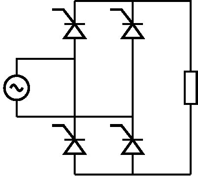
Circuit diagram
Another interesting use case is to display simple circuit diagrams which provides some insight for the user in to the operation of the device which uses the display. The circuit diagram can change depending upon the current operating mode of the device.
First the circuit diagram has been created using LaTeX and circuitikz. This provides us with a PDF. The lines and components has been made thicker to improve the results from the resizing and conversion to an image file.
\documentclass[]{standalone}
\usepackage[utf8]{inputenc}
\usepackage[T1]{fontenc}
\usepackage{amsmath}
\usepackage{amssymb}
\usepackage{graphicx}

\usepackage{circuitikz}

\usepackage[english]{babel}
\author{Eirik Haustveit}
\begin{document}

    \ctikzset{bipoles/thickness=1}
    \begin{circuitikz}[line width=2pt]
            \draw (0,0) coordinate(origo) to[vsourcesin] ++(0,2) to[short] ++(2,0) coordinate(in-top);
            \draw (origo) to[short] ++(4,0) coordinate(in-bot);

            \draw (in-top) to[thyristor] ++(0,2) coordinate(out-top-1);
            \draw (in-top) to[short] ++(0,-2) to[thyristor,invert,mirror] ++(0,-2) coordinate(out-bot-1);

            \draw (in-bot) to[thyristor,invert,mirror] ++(0,-2);
            \draw (in-bot) to[short] ++(0,2) to[thyristor] ++(0,2);

            \draw (out-top-1) to[short] ++(4,0) to[R,european] ++(0,-6);
            \draw (out-bot-1) to[short] ++(4,0);
    \end{circuitikz}


\end{document}
Conversion from PDF to image (in pbm format) is performed by issuing the following command:
pdftoppm single-phase-thyristor-converter.pdf single-phase-thyristor-converter -mono
After also converting to PNG this results in the following image:
We the use the same procedure as previously to resize the image and trim it if needed. After that, some manual editing was required before the diagram looked presentable. The following tiny image is the resulting BMP file after manual editing, before converting to XBM:

The following XBM listing provides the final image of the single phase thyristor converter:
#define single_phase_thyristor_converter_res_width 72
#define single_phase_thyristor_converter_res_height 64
static unsigned char single_phase_thyristor_converter_res_bits[] = {
    0x00, 0x00, 0x00, 0xF8, 0xFF, 0xFF, 0xFF, 0xFF, 0x3F, 0x00, 0x00, 0x00,
    0x08, 0x00, 0x00, 0x01, 0x00, 0x20, 0x00, 0x00, 0x00, 0x08, 0x00, 0x00,
    0x01, 0x00, 0x20, 0x00, 0x00, 0xF8, 0x08, 0x00, 0x1F, 0x01, 0x00, 0x20,
    0x00, 0x00, 0x80, 0x09, 0x00, 0x30, 0x01, 0x00, 0x20, 0x00, 0x00, 0x00,
    0x0B, 0x00, 0x60, 0x01, 0x00, 0x20, 0x00, 0x00, 0x00, 0x0E, 0x00, 0xC0,
    0x01, 0x00, 0x20, 0x00, 0x00, 0x00, 0x0C, 0x00, 0x80, 0x01, 0x00, 0x20,
    0x00, 0x00, 0x00, 0x7F, 0x00, 0xE0, 0x0F, 0x00, 0x20, 0x00, 0x00, 0x00,
    0x1C, 0x00, 0x80, 0x03, 0x00, 0x20, 0x00, 0x00, 0x00, 0x36, 0x00, 0xC0,
    0x06, 0x00, 0x20, 0x00, 0x00, 0x00, 0x63, 0x00, 0x60, 0x0C, 0x00, 0x20,
    0x00, 0x00, 0x00, 0x41, 0x00, 0x20, 0x08, 0x00, 0x20, 0x00, 0x00, 0x00,
    0x7F, 0x00, 0xE0, 0x0F, 0x00, 0x20, 0x00, 0x00, 0x00, 0x08, 0x00, 0x00,
    0x01, 0x00, 0x20, 0x00, 0x00, 0x00, 0x08, 0x00, 0x00, 0x01, 0x00, 0x20,
    0x00, 0x00, 0x00, 0x08, 0x00, 0x00, 0x01, 0x00, 0x20, 0x00, 0x00, 0x00,
    0x08, 0x00, 0x00, 0x01, 0x00, 0x20, 0x00, 0x00, 0x00, 0x08, 0x00, 0x00,
    0x01, 0x00, 0x20, 0x00, 0x00, 0x00, 0x08, 0x00, 0x00, 0x01, 0x00, 0x20,
    0x00, 0x00, 0x00, 0x08, 0x00, 0x00, 0x01, 0x00, 0x20, 0xC0, 0xFF, 0xFF,
    0x0F, 0x00, 0x00, 0x01, 0x00, 0x20, 0x40, 0x00, 0x00, 0x08, 0x00, 0x00,
    0x01, 0x00, 0x20, 0x40, 0x00, 0x00, 0x08, 0x00, 0x00, 0x01, 0x00, 0x20,
    0x40, 0x00, 0x00, 0x08, 0x00, 0x00, 0x01, 0x00, 0x20, 0x40, 0x00, 0x00,
    0x08, 0x00, 0x00, 0x01, 0x00, 0x20, 0x40, 0x00, 0x00, 0x08, 0x00, 0x00,
    0x01, 0x00, 0xF8, 0xF0, 0x00, 0x00, 0x08, 0x00, 0x00, 0x01, 0x00, 0x88,
    0x9C, 0x03, 0x00, 0x08, 0x00, 0x00, 0x01, 0x00, 0x88, 0x04, 0x02, 0x00,
    0x08, 0x00, 0x00, 0x01, 0x00, 0x88, 0x16, 0x06, 0x00, 0x08, 0x00, 0x00,
    0x01, 0x00, 0x88, 0x3A, 0x04, 0x00, 0x08, 0x00, 0x00, 0x01, 0x00, 0x88,
    0xC2, 0x05, 0x00, 0x08, 0x00, 0x00, 0x01, 0x00, 0x88, 0x86, 0x06, 0x00,
    0x08, 0x00, 0x00, 0x01, 0x00, 0x88, 0x04, 0x02, 0x00, 0x08, 0x00, 0x00,
    0x01, 0x00, 0x88, 0x9C, 0x03, 0x00, 0x08, 0x00, 0x00, 0x01, 0x00, 0x88,
    0xF0, 0x00, 0x00, 0x08, 0x00, 0x00, 0x01, 0x00, 0x88, 0x40, 0x00, 0x00,
    0x08, 0x00, 0x00, 0x01, 0x00, 0xF8, 0x40, 0x00, 0x00, 0x08, 0x00, 0x00,
    0x01, 0x00, 0x20, 0x40, 0x00, 0x00, 0x08, 0x00, 0x00, 0x01, 0x00, 0x20,
    0x40, 0x00, 0x00, 0x08, 0x00, 0x00, 0x01, 0x00, 0x20, 0x40, 0x00, 0x00,
    0x08, 0x00, 0x00, 0x01, 0x00, 0x20, 0xC0, 0xFF, 0xFF, 0xFF, 0xFF, 0xFF,
    0x01, 0x00, 0x20, 0x00, 0x00, 0x00, 0x08, 0x00, 0x00, 0x01, 0x00, 0x20,
    0x00, 0x00, 0x00, 0x08, 0x00, 0x00, 0x01, 0x00, 0x20, 0x00, 0x00, 0xF8,
    0x08, 0x00, 0x1F, 0x01, 0x00, 0x20, 0x00, 0x00, 0x80, 0x09, 0x00, 0x30,
    0x01, 0x00, 0x20, 0x00, 0x00, 0x00, 0x0B, 0x00, 0x60, 0x01, 0x00, 0x20,
    0x00, 0x00, 0x00, 0x0E, 0x00, 0xC0, 0x01, 0x00, 0x20, 0x00, 0x00, 0x00,
    0x0C, 0x00, 0x80, 0x01, 0x00, 0x20, 0x00, 0x00, 0x00, 0x7F, 0x00, 0xE0,
    0x0F, 0x00, 0x20, 0x00, 0x00, 0x00, 0x1C, 0x00, 0x80, 0x03, 0x00, 0x20,
    0x00, 0x00, 0x00, 0x36, 0x00, 0xC0, 0x06, 0x00, 0x20, 0x00, 0x00, 0x00,
    0x63, 0x00, 0x60, 0x0C, 0x00, 0x20, 0x00, 0x00, 0x00, 0x41, 0x00, 0x20,
    0x08, 0x00, 0x20, 0x00, 0x00, 0x00, 0x7F, 0x00, 0xE0, 0x0F, 0x00, 0x20,
    0x00, 0x00, 0x00, 0x08, 0x00, 0x00, 0x01, 0x00, 0x20, 0x00, 0x00, 0x00,
    0x08, 0x00, 0x00, 0x01, 0x00, 0x20, 0x00, 0x00, 0x00, 0x08, 0x00, 0x00,
    0x01, 0x00, 0x20, 0x00, 0x00, 0x00, 0x08, 0x00, 0x00, 0x01, 0x00, 0x20,
    0x00, 0x00, 0x00, 0x08, 0x00, 0x00, 0x01, 0x00, 0x20, 0x00, 0x00, 0x00,
    0x08, 0x00, 0x00, 0x01, 0x00, 0x20, 0x00, 0x00, 0x00, 0x08, 0x00, 0x00,
    0x01, 0x00, 0x20, 0x00, 0x00, 0x00, 0xF8, 0xFF, 0xFF, 0xFF, 0xFF, 0x3F,
    };
The following code listing provides a complete example on how to display the image on a LC-display:
#include <Arduino.h>
#include <U8g2lib.h>

#ifdef U8X8_HAVE_HW_SPI
#include <SPI.h>
#endif
#ifdef U8X8_HAVE_HW_I2C
#include <Wire.h>
#endif

#define single_phase_thyristor_converter_res_width 72
#define single_phase_thyristor_converter_res_height 64
static unsigned char single_phase_thyristor_converter_res_bits[] = {
  0x00, 0x00, 0x00, 0xF8, 0xFF, 0xFF, 0xFF, 0xFF, 0x3F, 0x00, 0x00, 0x00,
  0x08, 0x00, 0x00, 0x01, 0x00, 0x20, 0x00, 0x00, 0x00, 0x08, 0x00, 0x00,
  0x01, 0x00, 0x20, 0x00, 0x00, 0xF8, 0x08, 0x00, 0x1F, 0x01, 0x00, 0x20,
  0x00, 0x00, 0x80, 0x09, 0x00, 0x30, 0x01, 0x00, 0x20, 0x00, 0x00, 0x00,
  0x0B, 0x00, 0x60, 0x01, 0x00, 0x20, 0x00, 0x00, 0x00, 0x0E, 0x00, 0xC0,
  0x01, 0x00, 0x20, 0x00, 0x00, 0x00, 0x0C, 0x00, 0x80, 0x01, 0x00, 0x20,
  0x00, 0x00, 0x00, 0x7F, 0x00, 0xE0, 0x0F, 0x00, 0x20, 0x00, 0x00, 0x00,
  0x1C, 0x00, 0x80, 0x03, 0x00, 0x20, 0x00, 0x00, 0x00, 0x36, 0x00, 0xC0,
  0x06, 0x00, 0x20, 0x00, 0x00, 0x00, 0x63, 0x00, 0x60, 0x0C, 0x00, 0x20,
  0x00, 0x00, 0x00, 0x41, 0x00, 0x20, 0x08, 0x00, 0x20, 0x00, 0x00, 0x00,
  0x7F, 0x00, 0xE0, 0x0F, 0x00, 0x20, 0x00, 0x00, 0x00, 0x08, 0x00, 0x00,
  0x01, 0x00, 0x20, 0x00, 0x00, 0x00, 0x08, 0x00, 0x00, 0x01, 0x00, 0x20,
  0x00, 0x00, 0x00, 0x08, 0x00, 0x00, 0x01, 0x00, 0x20, 0x00, 0x00, 0x00,
  0x08, 0x00, 0x00, 0x01, 0x00, 0x20, 0x00, 0x00, 0x00, 0x08, 0x00, 0x00,
  0x01, 0x00, 0x20, 0x00, 0x00, 0x00, 0x08, 0x00, 0x00, 0x01, 0x00, 0x20,
  0x00, 0x00, 0x00, 0x08, 0x00, 0x00, 0x01, 0x00, 0x20, 0xC0, 0xFF, 0xFF,
  0x0F, 0x00, 0x00, 0x01, 0x00, 0x20, 0x40, 0x00, 0x00, 0x08, 0x00, 0x00,
  0x01, 0x00, 0x20, 0x40, 0x00, 0x00, 0x08, 0x00, 0x00, 0x01, 0x00, 0x20,
  0x40, 0x00, 0x00, 0x08, 0x00, 0x00, 0x01, 0x00, 0x20, 0x40, 0x00, 0x00,
  0x08, 0x00, 0x00, 0x01, 0x00, 0x20, 0x40, 0x00, 0x00, 0x08, 0x00, 0x00,
  0x01, 0x00, 0xF8, 0xF0, 0x00, 0x00, 0x08, 0x00, 0x00, 0x01, 0x00, 0x88,
  0x9C, 0x03, 0x00, 0x08, 0x00, 0x00, 0x01, 0x00, 0x88, 0x04, 0x02, 0x00,
  0x08, 0x00, 0x00, 0x01, 0x00, 0x88, 0x16, 0x06, 0x00, 0x08, 0x00, 0x00,
  0x01, 0x00, 0x88, 0x2A, 0x04, 0x00, 0x08, 0x00, 0x00, 0x01, 0x00, 0x88,
  0x42, 0x05, 0x00, 0x08, 0x00, 0x00, 0x01, 0x00, 0x88, 0x86, 0x06, 0x00,
  0x08, 0x00, 0x00, 0x01, 0x00, 0x88, 0x04, 0x02, 0x00, 0x08, 0x00, 0x00,
  0x01, 0x00, 0x88, 0x9C, 0x03, 0x00, 0x08, 0x00, 0x00, 0x01, 0x00, 0x88,
  0xF0, 0x00, 0x00, 0x08, 0x00, 0x00, 0x01, 0x00, 0x88, 0x40, 0x00, 0x00,
  0x08, 0x00, 0x00, 0x01, 0x00, 0xF8, 0x40, 0x00, 0x00, 0x08, 0x00, 0x00,
  0x01, 0x00, 0x20, 0x40, 0x00, 0x00, 0x08, 0x00, 0x00, 0x01, 0x00, 0x20,
  0x40, 0x00, 0x00, 0x08, 0x00, 0x00, 0x01, 0x00, 0x20, 0x40, 0x00, 0x00,
  0x08, 0x00, 0x00, 0x01, 0x00, 0x20, 0xC0, 0xFF, 0xFF, 0xFF, 0xFF, 0xFF,
  0x01, 0x00, 0x20, 0x00, 0x00, 0x00, 0x08, 0x00, 0x00, 0x01, 0x00, 0x20,
  0x00, 0x00, 0x00, 0x08, 0x00, 0x00, 0x01, 0x00, 0x20, 0x00, 0x00, 0xF8,
  0x08, 0x00, 0x1F, 0x01, 0x00, 0x20, 0x00, 0x00, 0x80, 0x09, 0x00, 0x30,
  0x01, 0x00, 0x20, 0x00, 0x00, 0x00, 0x0B, 0x00, 0x60, 0x01, 0x00, 0x20,
  0x00, 0x00, 0x00, 0x0E, 0x00, 0xC0, 0x01, 0x00, 0x20, 0x00, 0x00, 0x00,
  0x0C, 0x00, 0x80, 0x01, 0x00, 0x20, 0x00, 0x00, 0x00, 0x7F, 0x00, 0xE0,
  0x0F, 0x00, 0x20, 0x00, 0x00, 0x00, 0x1C, 0x00, 0x80, 0x03, 0x00, 0x20,
  0x00, 0x00, 0x00, 0x36, 0x00, 0xC0, 0x06, 0x00, 0x20, 0x00, 0x00, 0x00,
  0x63, 0x00, 0x60, 0x0C, 0x00, 0x20, 0x00, 0x00, 0x00, 0x41, 0x00, 0x20,
  0x08, 0x00, 0x20, 0x00, 0x00, 0x00, 0x7F, 0x00, 0xE0, 0x0F, 0x00, 0x20,
  0x00, 0x00, 0x00, 0x08, 0x00, 0x00, 0x01, 0x00, 0x20, 0x00, 0x00, 0x00,
  0x08, 0x00, 0x00, 0x01, 0x00, 0x20, 0x00, 0x00, 0x00, 0x08, 0x00, 0x00,
  0x01, 0x00, 0x20, 0x00, 0x00, 0x00, 0x08, 0x00, 0x00, 0x01, 0x00, 0x20,
  0x00, 0x00, 0x00, 0x08, 0x00, 0x00, 0x01, 0x00, 0x20, 0x00, 0x00, 0x00,
  0x08, 0x00, 0x00, 0x01, 0x00, 0x20, 0x00, 0x00, 0x00, 0x08, 0x00, 0x00,
  0x01, 0x00, 0x20, 0x00, 0x00, 0x00, 0xF8, 0xFF, 0xFF, 0xFF, 0xFF, 0x3F,
  };

U8G2_KS0108_128X64_1 u8g2(U8G2_R2, 4, 5, 6, 7, 8, 9, 10, 11, /*enable=*/ A1, /*dc=*/ A2, /*cs0=*/ A3, /*cs1=*/ A4, /*cs2=*/ U8X8_PIN_NONE, /* reset=*/  A0); 	// Set R/W to low!


void setup(void) {
  u8g2.begin();
}

u8g2_uint_t x = 0;
uint8_t load_current = 0;
uint8_t alpha = 0;

void loop(void) {

  // Counters to simulate some changing values (e.g. measurements).
  load_current += 1;
  alpha += 1;
  if(load_current > 50){
    load_current = 0;
  }
  if(alpha > 180){
    alpha = 0;
  }
  //u8g2.setFont(u8g2_font_ncenB10_tr);
  //u8g2.setFont(u8g2_font_5x7_tf);
  //u8g2.setFont(u8g2_font_nine_by_five_nbp_t_all);
  //u8g2.setFont(u8g2_font_mercutio_basic_nbp_t_all);

  u8g2.firstPage();
  do {

    u8g2.drawXBM(0,0, single_phase_thyristor_converter_res_width, single_phase_thyristor_converter_res_height, single_phase_thyristor_converter_res_bits);

    u8g2.setFont(u8g2_font_micro_mr);
    char buffer[32];
    snprintf(buffer, sizeof(buffer), "I = %i A", load_current);
    u8g2.drawStr(75, 20, buffer);

    snprintf(buffer, sizeof(buffer), "%i V", load_current*3);
    u8g2.drawUTF8(0, 50, buffer);

    snprintf(buffer, sizeof(buffer), "Ud = %i V", load_current*3);
    u8g2.drawUTF8(75, 35, buffer);

    snprintf(buffer, sizeof(buffer), "Mod: Einfase");
    u8g2.drawUTF8(80, 5, buffer);


    u8g2.setFont(u8g2_font_mozart_nbp_t_all);
    //u8g2.setFont(u8g2_font_courR08_tf);

    snprintf(buffer, sizeof(buffer), "α = %i°", alpha);
    u8g2.drawUTF8(80, 50, buffer);
    snprintf(buffer, sizeof(buffer), "P = %i%%", 100 - (((uint16_t)alpha * 100)/180));
    u8g2.drawUTF8(80, 60, buffer);


  } while ( u8g2.nextPage() );
  delay(10);
}
Footnotes
- 1
A LC-display is often erroneously referred to as a LCD-display. This kind of cognitive error is known as RAS syndrome (redundant acronym syndrome syndrome).