Additional material for lesson 5
Detailed look at the Atmega328p ADC
In the ADC hardware of the Atmega328p, there are many different parameters that needs to be configured properly. For example setting the ADC speed, resolution, conversion mode etc. By using the analogRead(analogPin) Arduino function without changing anything, we simply accept the parameters that the Arduino developers hav selected for us. The default settings are fine for basic usage, but there are many situations where you would have to go in to the details.
Voltage reference for the ADC
As discussed previously, the analog to digital converter uses a voltage reference for comparison with the analog signal it is converting. The Atmega328p microcontroller has several options for where to obtain this reference. In the Arduino UNO library these reference options may be set by the analogReference() function, which takes the parameters DEFAULT, INTERNAL, or EXTERNAL, for 5V, 1.1V or externally applied voltage to the AREF-pin respectively. The selected reference voltage will be the maximum input voltage for the ADC, i.e. the voltage that will correspond to the digital value of 1023.
analogReference(EXTERNAL);
If you are only interested in measuring voltages from 0 - 2 V, a external reference of 2 V will provide better resolution than the default reference of 5 V.
The accuracy of the reference voltage directly affects the accuracy of the converted voltage, and this is another motive for using an external reference. By accuracy in this context we mean: how sure can you be that the voltage actually is 5 V, is it 5.00 V, or could it be 5.02 V? A highly precise reference voltage can be used if high accuracy is required.
ADC conversion speed
The conversion speed is determined by the clock signal to the successive approximation register in the ADC. There is a maximum limit to this clock, after which the ADC starts misbehaving. The recommended maximum clock speed is 200 kHz, while the specified absolute maximum speed is 1 Mhz.
In the Arduino library the clock is derived from the CPU clock by using a prescaler of 128
Each conversion takes 13 ADC clock cycles, which yields a sample rate of:
The conversion time is thus given by:
This corresponds well with the conversion time stated in the documentation for the analogRead() function in the Arduino library.
Low level control of the Analog to Digital Conversion
Here is an example of the implementation of ADC without using built-in analogRead(analogPin) function. There are different ways of bitwise operations. It is better to be consistent in using one way but here we would like to see different ways. Let’s understand it with the help of Atmega328p datasheet.
#include <Arduino.h>

#define BAUDRATE 9600

void init_ports(void);
void init_adc(void);
unsigned char read_ADC(uint8_t);

void setup() {
  init_adc();
  Serial.begin(BAUDRATE);
}

void loop() {
  uint16_t adc_val = adc_read(0);
  Serial.print("ADC value:");
  Serial.println(adc_val);
  delay(100);

}

void init_adc(void)
{
  ADMUX = (1 << REFS0); //default Ch-0; Vref = 5V
  //ADMUX = ADMUX | 0x20;   // set for Left Justified
  ADCSRA |= (1 << ADEN) | (0 << ADSC) | (0 << ADATE); //auto-trigger OFF -- EXERCISE:how to write in hexadecimal?
  ADCSRB = 0x00;
}

uint16_t adc_read(uint8_t pin)
{
  static uint16_t value;

  // select the corresponding channel 0~7
  // ANDing with '7′ will always keep the value of pin between 0 and 7
  pin &= 0b00000111;  // AND operation with 7 // pin &= 0x07 // pin = pin & 7
  ADMUX = (ADMUX & 0xF8)|pin; // setting MUX[0:3]

  // start single convertion
  ADCSRA |= (1 << ADSC);

  // wait for conversion to complete
  // ADSC becomes '0′ again
  while ((ADCSRA & 0x10) == 0); // until the flag is reset again // while(ADCSRA & (1 << ADSC))
  value = (ADCL | (ADCH << 8)); //10-bit data

  return value;
}
Note
ADC is a demanding topic also requires basic signal processing knowledge. One should read about possible errors before computing a serious analog to digital conversion. Here, is a very nice summary of general ADC problems.
While the main function of the analog pins for most Arduino users is to read analog sensors, the analog pins also have all the functionality of general purpose input/output (GPIO) pins (the same as digital pins 0 - 13). Consequently, if a user needs more general purpose input output pins, and all the analog pins are not in use, the analog pins may be used for GPIO.
Warning
The analogRead function will not work correctly if a pin has been previously set to an output, so if this is the case, set it back to an input before using analogRead. Similarly if the pin has been set to HIGH as an output, the pull-up resistor will be set, when switched back to an input.
The ATmega datasheet also cautions against switching analog pins in close temporal proximity to making A/D readings (analogRead) on other analog pins. This can cause electrical noise and introduce jitter in the analog system. It may be desirable, after manipulating analog pins (in digital mode), to add a short delay before using analogRead() to read other analog pins.
Increasing resolution by oversampling
Todo
Explain how to use oversampling (and why it works)
Servo Motor Drive
There is no principal difference between a servo motor and any other kind of motor. The difference lies in how one intends to use it. A servo motor is intended for precise control of angular or linear position, and thus it typically employs a position sensor on the shaft. Traditionally brushed DC-motors have been the preferred choice for servo motors, due to the ease of control. Today however there are many different classes of motors that are used for servo application.
The Arduino starter kit contains a special servo motor SM-S2309S which has some features that are quite usefull for many servo applications. It has a built in gearbox that reduces the speed and increases the torque on the shaft, and a built in position sensor, wich allows us to simply request a potion, and the motor will move to that position.
The following video gives a good explanation to the internal operation of this kind of servo motor.
Switching frequency
The analogWrite() function in the standard Arduino library only support one parameter, specifying the duty cycle of the generated PWM output. Another important parameter of PWM however is the frequency at wich the pulses are turned on and off. The Arduino library does not support changing this frequency, but it is possible to change it by accessing the registers of the timers responsible for generating the PWM.
Warning
Changing the registers may impact the operation of other features of the Arduino library, such as the millis() function.
The various hardware timers in the microcontroller are responsible for various groups of PWM outputs. Thus by manipulating a given hardware timer, you will be manipulating the frequency of some of the PWM outputs.
pinMode(3, OUTPUT);
pinMode(11, OUTPUT);
TCCR2A = _BV(COM2A1) | _BV(COM2B1) | _BV(WGM21) | _BV(WGM20);
TCCR2B = _BV(CS22);
OCR2A = 180;
OCR2B = 50;
Servo motor library
Servo motors typically requires 20ms period of PWM signals (50Hz) with pulse width varying between 1ms-2ms (0-180 degrees) as a driving signal. Since the generic analogWrite() works in 490Hz/ 980Hz, you cannot drive a servo motor unless you fiddle around the timer settings. Luckily, Arduino comes with a servo library that simplifies the control of the servo motor.
The following example shows how you may send commands on the serial UART to control the servo position. Given 5 different values via serial port, control the servo angle.
#include <Servo.h>

Servo myservo;  // create servo object to control a servo

int incomingByte = 0; // for incoming serial data

int val;    // variable to read the value from the serial port
int mappedVal;

void setup() {
  myservo.attach(9);  // attaches the servo on pin 9 to the servo object
  Serial.begin(9600); // opens serial port, sets data rate to 9600 bps
}

void loop() {

  if (Serial.available() > 0) {
    val = Serial.read() - 48;            // reads the value from the serial port. (-48 is for ascii conversion)
    mappedVal = map(val, 0, 5, 0, 180);     // scale it to use it with the servo (value between 0 and 180)
    Serial.print("I received: ");
    Serial.println(mappedVal);
    myservo.write(mappedVal);                  // sets the servo position according to the scaled value
    delay(15);          // waits for the servo to get there
  }
}


/*
////////////////////////////////////////////////////
//      COMPARISON WITH analogWrite()             //
////////////////////////////////////////////////////

int incomingByte = 0; // for incoming serial data

int val;    // variable to read the value from the serial port
int mappedVal;

const int myservo_pin = 9;

void setup() {
  Serial.begin(9600); // opens serial port, sets data rate to 9600 bps
  pinMode(myservo_pin, OUTPUT);
}

void loop() {

  if (Serial.available() > 0) {
    val = Serial.read() - 48;            // reads the value from the serial port. (-48 is for ascii conversion)
    mappedVal = map(val, 0, 5, 0, 180);     // scale it to use it with the servo (value between 0 and 180)
    Serial.print("I received: ");
    Serial.println(mappedVal);
    //myservo.write(mappedVal);                  // sets the servo position according to the scaled value
    analogWrite(myservo_pin, mappedVal);
    delay(15);          // waits for the servo to get there
  }
}
*/
We talked about that we drive servo motors using PWM signal but also we didn’t use the regular analogWrite() function. It wouldn’t work. Let’s see the difference of the signal types between analogWrite() and myservo.write() using a logic analyzer.
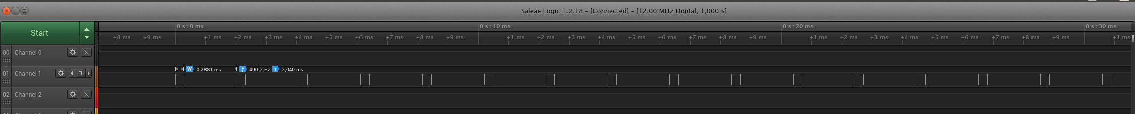
Logic Analyzer result for analogWrite() function

Logic Analyzer result for myservo.write() function
Servo motor drive example
The following example uses a push button to toggle through various positions on the servo motor.
#include <Arduino.h>
#include <Servo.h>

const uint8_t toggle_button_pin = 12;

Servo robot_arm;

uint8_t toggle_button_event();

void setup() {
  pinMode(toggle_button_pin, INPUT);
  robot_arm.attach(3);
  Serial.begin(9600);
}

void loop() {

  static uint8_t motor_pos = 0;

  if(toggle_button_event()){
    motor_pos += 10;

    Serial.println("+10 grader.");
    Serial.println(motor_pos);
    if(motor_pos > 180){
      motor_pos = 0;
    }
  }

  robot_arm.write(motor_pos);
  //delay(500);
}

uint8_t toggle_button_event(){

  static uint16_t shift_register = 0;
  static uint32_t old_millis = 0;

  if(millis() > old_millis + 5){

    old_millis = millis();

    uint8_t input_state = digitalRead(toggle_button_pin);

    shift_register = (shift_register << 1) | input_state | 0xC000;

    if(shift_register == 0xE000){
      Serial.print("Start event detected.");
      return 1;
    }
  }
  return 0;
}