Arduino Introduction
Arduino is an open-source electronics platform based on easy-to-use hardware and software. Arduino boards are able to read inputs - light on a sensor, a finger on a button, or a Twitter message - and turn it into an output - activating a motor, turning on an LED, publishing something online. You can tell your board what to do by sending a set of instructions to the microcontroller on the board. To do so you use the Arduino programming language (based on Wiring), and the Arduino Software (IDE), based on Processing.
Over the years Arduino has been the brain of thousands of projects, from everyday objects to complex scientific instruments. A worldwide community of makers - students, hobbyists, artists, programmers, and professionals - has gathered around this open-source platform, their contributions have added up to an incredible amount of accessible knowledge that can be of great help to novices and experts alike.
Arduino was born at the Ivrea Interaction Design Institute as an easy tool for fast prototyping, aimed at students without a background in electronics and programming. As soon as it reached a wider community, the Arduino board started changing to adapt to new needs and challenges, differentiating its offer from simple 8-bit boards to products for IoT applications, wearable, 3D printing, and embedded environments. All Arduino boards are completely open-source, empowering users to build them independently and eventually adapt them to their particular needs. The software, too, is open-source, and it is growing through the contributions of users worldwide.
I don’t want to scare you in the first course :) I just wanted to show you how powerful tool you are gonna learn to use. Of course we will not cover all of the capabilities of Arduino right now. We will see very fundamental applications in this course. By carrying them out, we will improve our programming skills. Depending on the enthusiasm of you in general, We are planning to achieve really good projects!
Arduino Software
Installation of the Arduino software has already been covered in a previous lesson. The Arduino Software (or Integrated Development Environment - IDE) allows you to write programs and upload them to your board.
The Language reference and the built-in examples are invaluable resources when developing your own programs.
Furthermore the following resources can be of great help (although they should be read with dubious eyes, as some of them are open to contributions from anyone):
Also you can use Arduino forum to ask questions.
Let’s see if your installation works with a blink code Exercise: Blink an LED
Arduino Hardware
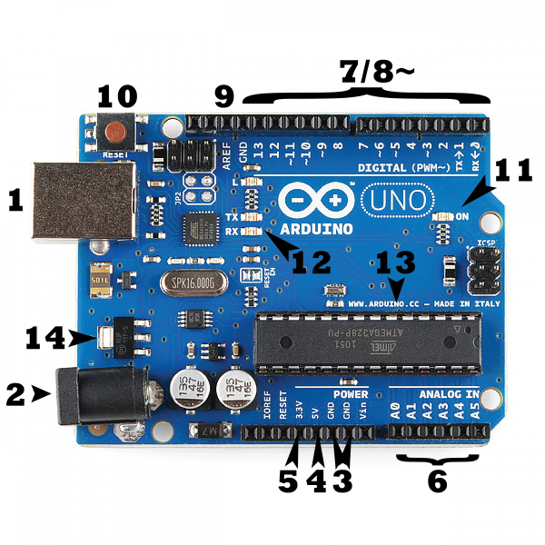
There are many varieties of Arduino boards (as we mention in the previous lecture notes) that can be used for different purposes. Some boards look a bit different from the one below, but most Arduinos have the majority of these components in common 5:
Warning
Be aware that you are fiddling around the electricity. Even though Arduino has a low current rating (Uno 1A, Nano 500mA, both 500mA when they are fed from USB), still you have to keep in mind that you can damage yourself, the board, or the products which you are working with.
Power (USB / Barrel Jack)
Every Arduino board needs a way to be connected to a power source. The Arduino UNO can be powered from a USB cable coming from your computer or a wall power supply that is terminated in a barrel jack. In the picture above the USB connection is labeled (1) and the barrel jack is labeled (2).
The USB connection also allows you to upload new firmware onto your Arduino board, as well as to communicate with the board while the firmware is running.
Warning
Do NOT use a power supply greater than 20 Volts as you will overpower (and thereby destroy) your Arduino. The recommended voltage for most Arduino models is between 6 and 12 Volts.
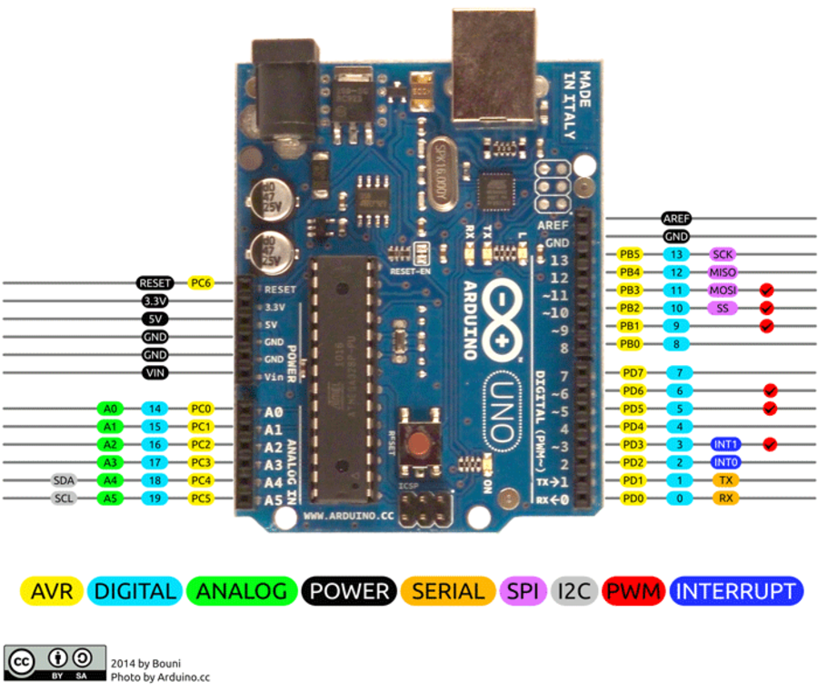
Pins (5V, 3.3V, GND, Analog, Digital, PWM, AREF)
The pins on your Arduino are the places where you connect wires to construct a circuit (probably in conjuction with a breadboard and some wire. They usually have black plastic ‘headers’ that allow you to just plug a wire right into the board. The Arduino has several different kinds of pins, each of which is labeled on the board and used for different functions.
GND (3): Short for ‘Ground’. There are several GND pins on the Arduino, any of which can be used to ground your circuit.
5V (4) & 3.3V (5): As you might guess, the 5V pin supplies 5 volts of power, and the 3.3V pin supplies 3.3 volts of power. Most of the simple components used with the Arduino run happily off of 5 or 3.3 volts.
Analog (6): The area of pins under the ‘Analog In’ label (A0 through A5 on the UNO) are Analog In pins. These pins can read the signal from an analog sensor (like a temperature sensor) and convert it into a digital value that we can read.
Digital (7): Across from the analog pins are the digital pins (0 through 13 on the UNO). These pins can be used for both digital input (like telling if a button is pushed) and digital output (like powering an LED).
PWM (8): You may have noticed the tilde (~) next to some of the digital pins (3, 5, 6, 9, 10, and 11 on the UNO). These pins act as normal digital pins, but can also be used for something called Pulse-Width Modulation (PWM). We have a tutorial on PWM, but for now, think of these pins as being able to simulate analog output (like fading an LED in and out).
AREF (9): Stands for Analog Reference. Most of the time you can leave this pin alone. It is sometimes used to set an external reference voltage (between 0 and 5 Volts) as the upper limit for the analog input pins.
Reset Button
Just like the original Nintendo, the Arduino has a reset button (10). Pushing it will temporarily connect the reset pin to ground and restart any code that is loaded on the Arduino. This can be very useful if your code doesn’t repeat, but you want to test it multiple times. Unlike the original Nintendo however, blowing on the Arduino doesn’t usually fix any problems.
Power LED Indicator
Just beneath and to the right of the word “UNO” on your circuit board, there’s a tiny LED next to the word ‘ON’ (11). This LED should light up whenever you plug your Arduino into a power source. If this light doesn’t turn on, there’s a good chance something is wrong. Time to re-check your circuit!
TX RX LEDs
TX is short for transmit, RX is short for receive. These markings appear quite a bit in electronics to indicate the pins responsible for serial communication. In our case, there are two places on the Arduino UNO where TX and RX appear – once by digital pins 0 and 1, and a second time next to the TX and RX indicator LEDs (12). These LEDs will give us some nice visual indications whenever our Arduino is receiving or transmitting data (like when we’re loading a new program onto the board).
Main IC
The black thing with all the metal legs is an IC, or Integrated Circuit (13). Think of it as the brains of our Arduino. The main IC on the Arduino is slightly different from board type to board type, but is usually from the ATmega line of IC’s from the ATMEL company, although some new boards are appearing which use different microcontrollers. This can be important, as you may need to know the IC type (along with your board type) before loading up a new program from the Arduino software. This information can usually be found in writing on the top side of the IC. If you want to know more about the difference between various IC’s, reading the datasheets is often a good idea.
Voltage Regulator
The voltage regulator (14) is not actually something you can (or should) interact with on the Arduino. But it is potentially useful to know that it is there and what it’s for. The voltage regulator does exactly what it says – it controls the amount of voltage that is let into the Arduino board. Think of it as a kind of gatekeeper; it will turn away an extra voltage that might harm the circuit. Of course, it has its limits, so don’t hook up your Arduino to anything greater than 20 volts.
Memory in Arduino
There are three pools of memory in the microcontroller used on avr-based Arduino boards:
Flash memory (program space), is where the Arduino sketch is stored.
SRAM (static random access memory) is where the sketch creates and manipulates variables when it runs.
EEPROM is memory space that programmers can use to store long-term information.
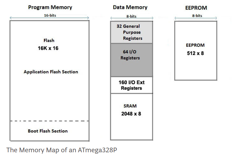
Flash memory and EEPROM memory are non-volatile (the information persists after the power is turned off). SRAM is volatile and will be lost when the power is cycled.
The ATmega328 chip found on the Uno has the following amounts of memory:
Flash 32k bytes (of which .5k is used for the bootloader)
SRAM 2k bytes
EEPROM 1k byte
The ATmega2560 in the Mega2560 has larger memory space :
Flash 256k bytes (of which 8k is used for the bootloader)
SRAM 8k bytes
EEPROM 4k byte
Notice that there’s not much SRAM available in the Uno. It’s easy to use it all up by having lots of strings in your program. For example, a declaration like:
char message[] = "I am a very skilled programmer as you see.";
puts 42 bytes into SRAM (each character takes a byte, plus the terminator character). This might not seem like a lot, but it doesn’t take long to get to 2048, especially if you have a large amount of text to send to a display, or a large lookup table, for example.
If you run out of SRAM, your program may fail in unexpected ways; it will appear to upload successfully, but not run, or run strangely. To check if this is happening, you can try commenting out or shortening the strings or other data structures in your sketch (without changing the code). If it then runs successfully, you’re probably running out of SRAM. There are a few things you can do to address this problem:
If your arduino software talks to a program running on a (desktop/laptop) computer, you can try shifting data or calculations to the computer, reducing the load on the Arduino. If you have lookup tables or other large arrays, use the smallest data type necessary to store the values you need; for example, an int takes up two bytes, while a byte uses only one (but can store a smaller range of values). If you don’t need to modify the strings or data while your sketch is running, you can store them in flash (program) memory instead of SRAM; to do this, use the PROGMEM keyword. We will discuss this in more detail later in the course.
Finally if you need the microcontroller to be able to keep some data it is operating on after a power cycle you should use the EEPROM. See the EEPROM library.
Arduino Programming
The following code block shows the bare minimum that must be included in a Arduino sketch.
void setup() {
        // Setup stuff to only run once at the beginning
}
void loop()
{
        // This function gets called indefinitely
}
In addition to this bare minimum, any project using PlatformIO will have #include <Arduino.h> in order to import the required Arduino libraries. This is not required in the Arduino IDE, as this import happens “behind the scenes”. Thus in the PlatformIO case the bare minimum is:
#include <Arduino.h>

void setup() {

}

void loop() {

}
The Arduino UNO board
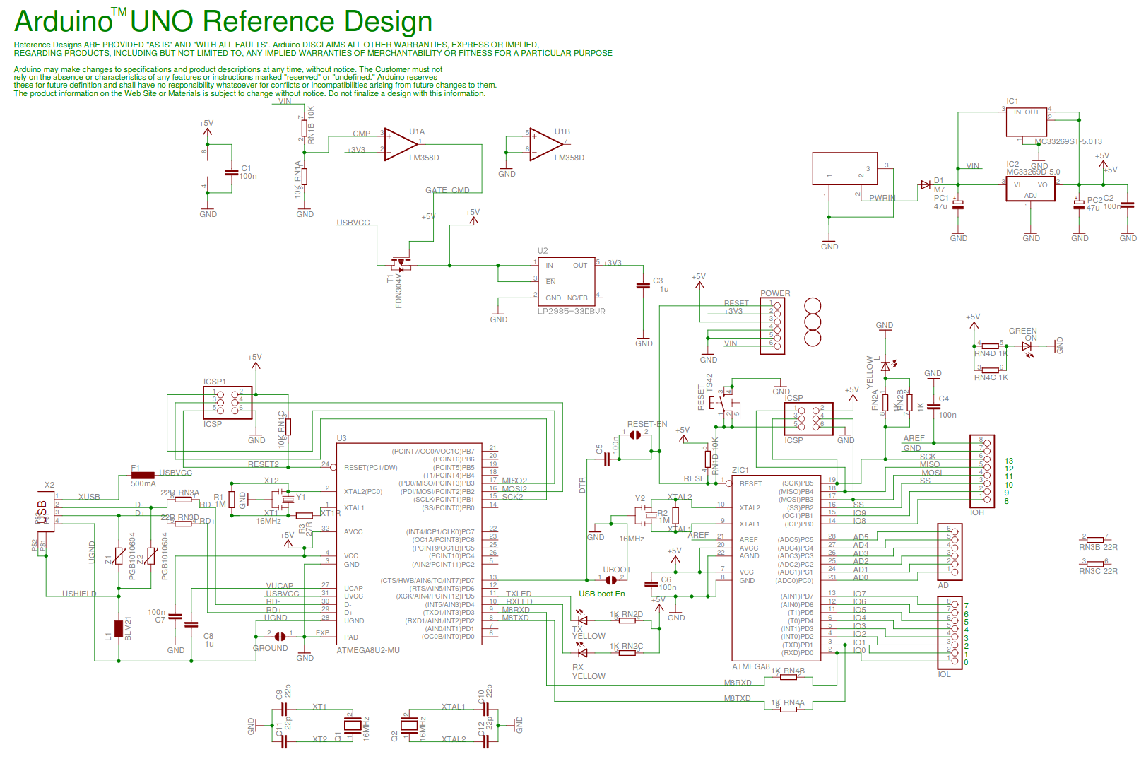
Arduino UNO (uno meaning “one” in Italian) was the first Arduino board to be released with onboard USB connector. It has the following schematic, which can be divided in to USB bridge, power, and microcontroller.
The Atmega328 microcontroller
The Arduino UNO uses the Atmega328 microcontroller. The processor in the Atmega328 is of the AVR architecture (AVR from the Norwegian inventors Alf-Egil and Vegard, and the acronym RISC (Reduced instruction set computer)).
The datasheet for the microcontroller contains many details about the features of the controller and how to use them. We will get back to some details in the datasheet in future lectures.
Exercise: Blink an LED
We already looked at a LED blink example as a initial test in the software installation lesson, but it is repeated here because the exercises which follows build upon the basic LED blinker.
It is tradition when introducing a new programming language on a PC that the first program simply prints the text ‘Hello, World!’ to the monitor 1. Many microcontrollers however are not equipped with a monitor, and even if they where, the code involved in writing text to this monitor would be to complicated for a first example (on a PC many of the low level details are hidden from the user). Thus the simple process of blinking a lamp (typically a LED) is often considered the ‘Hello, world’ of microcontrollers.
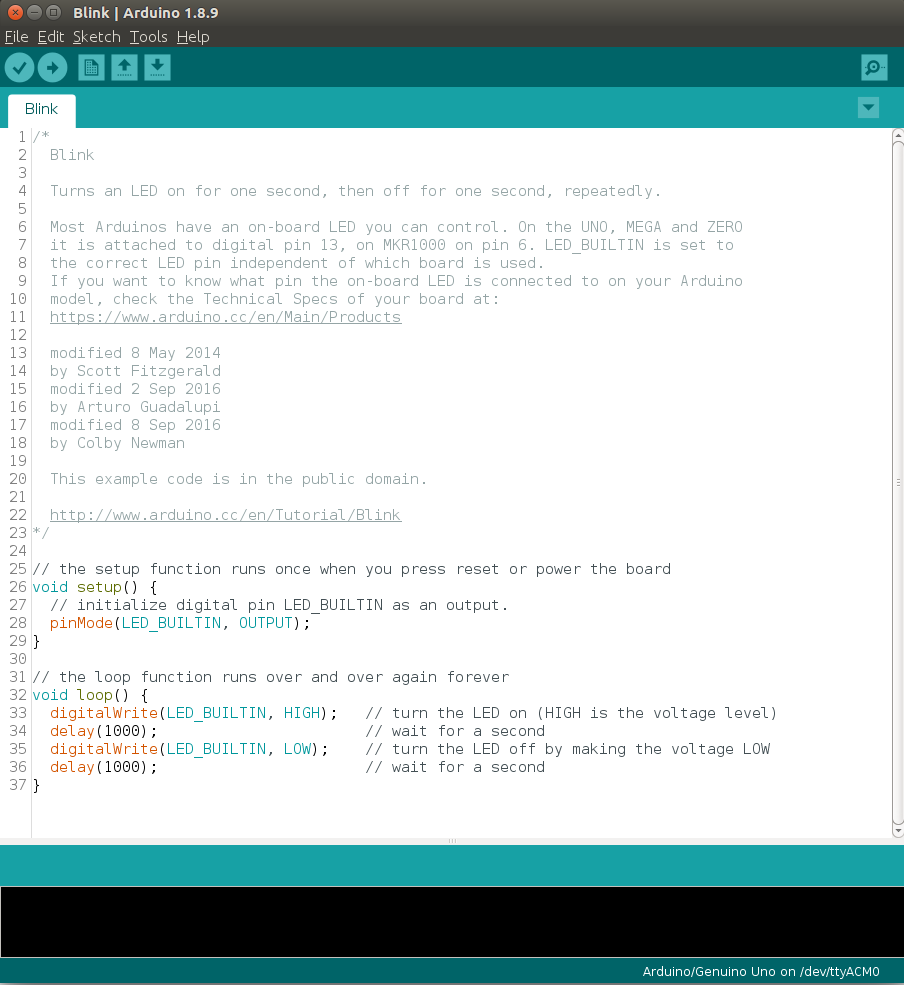
The following code is taken from the official Arduino distribution, and demonstrates how to blink a led connected to pin number 13 on the Arduino. This example continuously flashes an LED by writing HIGH and LOW outputs to a pin. In the next lesson we will learn more about the Arduino pins. When the sketch begins, the code in setup sets the pin mode (so it’s capable of lighting an LED). After the code in setup is completed, the code in loop is repeatedly called (to flash the LED) for as long as the Arduino board is powered on.
/*
 Blink
Turns on an LED on for one second, then off for one second, repeatedly.

This example code is in the public domain.
*/

// Pin 13 has an LED connected on most Arduino boards.
// give it a name:
int led = 13;

// the setup routine runs once when you press reset:
void setup() {
        // initialize the digital pin as an output.
        pinMode(led, OUTPUT);
}

// the loop routine runs over and over again forever:
void loop() {
        digitalWrite(led, HIGH);   // turn the LED on (HIGH is the voltage level)
        delay(1000);               // wait for a second
        digitalWrite(led, LOW);    // turn the LED off by making the voltage LOW
        delay(1000);               // wait for a second
}
Pin 13 on the Arduino UNO is connected to a onboard LED, which makes it convenient to use for this first test program.
Exercise: Blink using morse code
It this exercise we will use the LED to emit morse code. It is possible to create a function which takes text input, and automatically generate the corresponding morse code signals (and indeed such a function has been prepared as one of our larger examples which you will be exposed to later in the course). For this exercise however you are only expected to hard code the blinking using explicit calls to the write and delay functions.
Start by creating a new project, and copying your LED blink code from the previous project
Make the necessary modification in order to make the LED emit the morse signal for SOS.
Verify the operation of the program.
If you have time (and a short name), change the code so it emits your name as morse code.
Unless you already know the morse alphabet, use your favorite search engine to locate a table of all the characters. Write a program which outputs the correct blink pattern on an external LED. Remember to take into consideration the correct durations of each element in the code. A dash is three times as long as a dot, and the space between each mark (dash or dot) is the same length as a dot. By using a single variable to hold the duration of a dot, you can easily compute the other delays. This will allow you to adjust the transmission speed without having to do large changes to your code.
A person trained in decoding morse in the form of sound signals will not necessarily find it easy to decode the blinking light. One typically does not count dots and dashes, but rather identify the particular “sound” of a given symbol. For this to work the speed of transmission should not be to slow.
The traditional lamp used for blinking morse is known as an Aldis lamp, and is still in use by the navy for short range communication between ships:
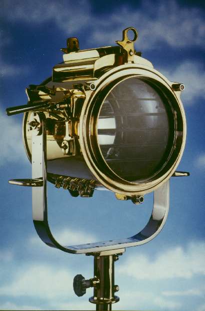
… to send long and short duration of light signals. For SOS:

The following code listing provides one possible solution to this exercise:
#include <Arduino.h>

#define RED_LED 4

#define DOT_LENGTH 200
#define SPACE DOT_LENGTH
#define DASH_LENGTH DOT_LENGTH * 3
#define LETTER_PAUSE DASH_LENGTH

void setup() {

  pinMode(RED_LED, OUTPUT);

}

void loop() {

/**
 * Send SOS
 * ... --- ...
*/

  // ...
  digitalWrite(RED_LED, HIGH);
  delay(DOT_LENGTH);
  digitalWrite(RED_LED, LOW);
  delay(SPACE);

  digitalWrite(RED_LED, HIGH);
  delay(DOT_LENGTH);
  digitalWrite(RED_LED, LOW);
  delay(SPACE);

  digitalWrite(RED_LED, HIGH);
  delay(DOT_LENGTH);
  digitalWrite(RED_LED, LOW);

  delay(LETTER_PAUSE);

  // ---
  digitalWrite(RED_LED, HIGH);
  delay(DASH_LENGTH);
  digitalWrite(RED_LED, LOW);
  delay(SPACE);

  digitalWrite(RED_LED, HIGH);
  delay(DASH_LENGTH);
  digitalWrite(RED_LED, LOW);
  delay(SPACE);

  digitalWrite(RED_LED, HIGH);
  delay(DASH_LENGTH);
  digitalWrite(RED_LED, LOW);

  delay(LETTER_PAUSE);

  // ...
  digitalWrite(RED_LED, HIGH);
  delay(DOT_LENGTH);
  digitalWrite(RED_LED, LOW);
  delay(SPACE);

  digitalWrite(RED_LED, HIGH);
  delay(DOT_LENGTH);
  digitalWrite(RED_LED, LOW);
  delay(SPACE);

  digitalWrite(RED_LED, HIGH);
  delay(DOT_LENGTH);
  digitalWrite(RED_LED, LOW);
  delay(LETTER_PAUSE);

  delay(4000);
}
Exercise: Blink an external LED
The above program may easily be modified to blink an external LED. The following figure shows how a LED may be connected to pin 3 of the Arduino UNO. The resistor is 220 Ohm, and is required in order to limit the current through the LED.
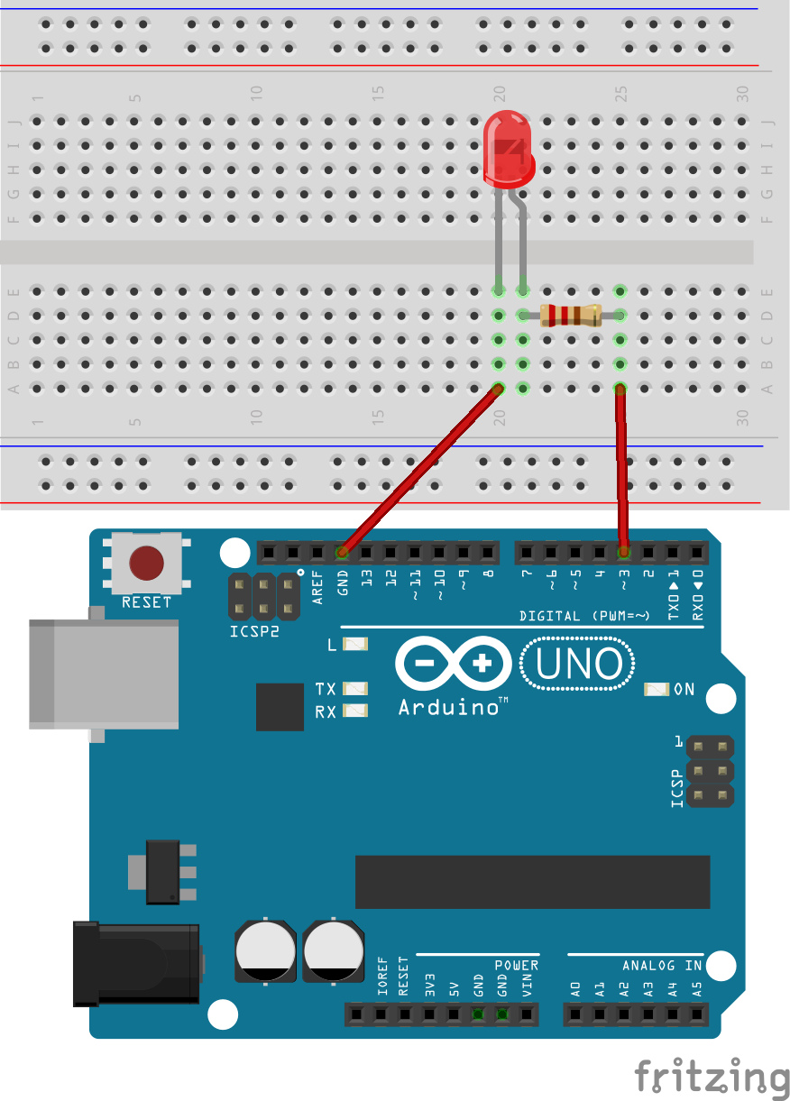
By changing the code int led = 13; to int led = 3;, the LED blink program or morse generation program, it will blink the LED in the figure.
Connect the external LED in accordance with the “schematic”.
Change the pin configuration to pin 3.
Verify the operation of the program, and your circuit.
In real life it should look like the following:
Exercise: Hello World
For those of you who finished the previous tasks, and did not like the LED blink alterative to “hello, world”, the following example illustrates how to do it properly:
void setup() {
        Serial.begin(9600);
}

void loop() {
        Serial.println("hello, world");
}
This will be covered thoroughly in the upcoming lecture, but it does not hurt to try it. Make sure you understand the LED blink example first though.
See also
Are you done with your Blink and HelloWorld? Can you print out the dots and dashes to the serial monitor while blinking?
Hint: use Serial.begin(9600), Serial.print().
The build and upload process (not mandatory to read)
When you press the upload button in the Arduino IDE the program goes through many steps before the program is ready to run on the microcontroller. Although it is often safe to ignore these low level details, it is also important to know about them when someting goes wrong. A thorough understanding of these steps will help you deduce the source of the error.
A detailed look at the Arduino software library
This last section is not part of the curriculum, but is included for those of you who have previous programming experience.
In standard C/C++ programs the first function to run is the ‘main()’ function. In Arduino however this has been changed into the ‘setup()’ function followed by the ‘loop()’ function. Behind the scenes however there is still a main function as shown in the following code.
/*
  main.cpp - Main loop for Arduino sketches
  Copyright (c) 2005-2013 Arduino Team.  All right reserved.
  This library is free software; you can redistribute it and/or
  modify it under the terms of the GNU Lesser General Public
  License as published by the Free Software Foundation; either
  version 2.1 of the License, or (at your option) any later version.
  This library is distributed in the hope that it will be useful,
  but WITHOUT ANY WARRANTY; without even the implied warranty of
  MERCHANTABILITY or FITNESS FOR A PARTICULAR PURPOSE.  See the GNU
  Lesser General Public License for more details.
  You should have received a copy of the GNU Lesser General Public
  License along with this library; if not, write to the Free Software
  Foundation, Inc., 51 Franklin St, Fifth Floor, Boston, MA  02110-1301  USA
*/

#include <Arduino.h>

// Declared weak in Arduino.h to allow user redefinitions.
int atexit(void (* /*func*/ )()) { return 0; }

// Weak empty variant initialization function.
// May be redefined by variant files.
void initVariant() __attribute__((weak));
void initVariant() { }

void setupUSB() __attribute__((weak));
void setupUSB() { }

int main(void)
{
        init();

        initVariant();

#if defined(USBCON)
        USBDevice.attach();
#endif

        setup();

        for (;;) {
                loop();
                if (serialEventRun) serialEventRun();
        }

        return 0;
}
The code above is automatically added to your project, and ensures that the setup() function is called once during boot, and that the loop() function is called again as soon as it can finish. In addition to the above code, the Arduino distribution has many other source files that by default are added to the project. This makes sure that functions such as ‘digitalWrite’, and ‘digitalRead’ are available for our convenience 3.
The preprocessor
The preprocessor looks for any line in the source code beginning with ‘#’. The text following the ‘#’ is interpreted as a special preprocessing command. E.g. the ‘#include <Arduino.h>’ in the above example code includes all the text in the file named ‘Arduino.h’. In addition any preprocessing commands occuring in the ‘Arduino.h’ file will also be processed.
The purpose of the preprocessor is to help manage large projects where the code is separated into different files, and where different parts of the code are needed at different times. E.g. some parts of the code may be needed for all Arduino versions, while others are specific to a given version, and should ideally automatically be excluded where it is not needed.
The compiler
A compiler is a program that translates source code from one programming language to another. For our purposes it is a translation from C/C++ to machine code that the microcontroller CPU is able to execute. Because the compiled program will run on a different CPU to the compiler, the process is refered to as cross-compiling.
The linker
Normally each source file in a project with multiple files is compiled into it’s own machine code file. This file is referred to as a object file, and all the object files must be combined to produce the final executable file. It is the purpose of the linker to perform this operation.
The output from the linker is a ELF (Executable and Linkable Format) file.
Generation of the HEX file
In the microcontroller flash memory, every byte of data must be written to the correct location for the program to operate as intended. The ELF file from the linker is translated to a so called Intel HEX file which conveys the binary data and the exact memory address for it to be written as ASCII text.
At this stage is is also possible to add additional binary data that is not a part of the program. E.g. a music file, or a image. In that case you should of course write the program to be able to access the additional data.
The upload process
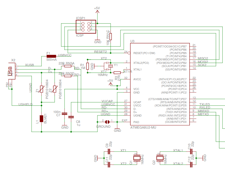
The Arduino UNO board has a USB connector used for communication as well as for uploading new programs. The complicated USB protocol is handled by a separate microcontroller Atmel ATMEGA16U2 that is running a program written for this purpose 2. Normally it is not required to modify the program on this additional microcontroller, but it is possible through a special procedure.
When power is applied to the microcontroller (or the controller is reset) the first instruction to be executed by the CPU is placed in the so called ‘reset vector’ memory location (at address 0x0000 on Atmega328). This instruction must be a relative jump instruction (RJMP) to move the instruction pointer to the address of the boot loader (or the main program if no bootloader is used).
On the Arduino the bootloader initially waits for a special sequence of bytes on the serial port. If the sequence is received the bootloader expects the following bytes to be a new program to be written to flash memory of the controller. If not such sequence is received the bootloader will issue a jump to the previously written program.
Covering the programming fundamentals
Continue the fundamentals in Arduino Cookbook by Michael Margolis from Chapter-2.
Footnotes
- 1
The ‘hello, world’ program was first introduced in the book “The C Programming Language” (sometimes termed K&R, after its authors’ initials) by Brian Kernighan and Dennis Ritchie.
- 2
Readers that are particulary interested can find the USB firware source code at github
- 3
The complete source code for the Arduino core can be found in the Official Arduino Core repository
References
- 4
https://www.arduino.cc/en/tutorial/memory - 21 January 2020.
- 5
https://learn.sparkfun.com/tutorials/what-is-an-arduino/whats-on-the-board - 21 January 2020