Additional material for lesson 7
Introduction
A interrupt is some form of external signal which interrupts the main process of the microcontroller CPU. When an interrupt occurs the current execution state of the main process is stored, before a different process (the ISR, or interrupt service routine) takes over. When the interrupt service routine has completed, execution control is returned to the main process. By external signal we mean a signal which is external to the CPU, physically it can be internal or external to the microcontroller chip. E.g. it can be generated by the timeout of an internal timer in the MCU, or by the change of logic state on a external pin.
Interrupts are useful for making the system responsive to external events while avoiding constant polling of the possible external event sources. The ISR may simply set a flag, or publish a message in a event queue such that the main process can take appropirate action when it is ready to do so.
The first section of this lecture describes how and when the interrupts are preferable over polling techniques. The following sections explain how the interrupt mechanism works. The second half of the lecture notes, starting with the section “Management of Interrupts,” describes the common problems and programming mistakes and their solutions in utilizing interrupts in typical microcontroller applications.
Timing in Microcontrollers
A timer is a specialized type of clock which is used to measure time intervals. A timer that counts from zero upwards for measuring time elapsed is often called a stopwatch. It is a device that counts down from a specified time interval and used to generate a time delay, for example, an hourglass is a timer.
A counter is a device that stores (and sometimes displays) the number of times a particular event or process occurred, with respect to a clock signal. It is used to count the events happening outside the microcontroller. In electronics, counters can be implemented quite easily using register-type circuits such as a flip-flop. 2
Timers are counters that can be programmed to perform a variety of functions. Following are the typical operation modes and possible applications of timers:
1. Programmed operation: A timer can be used as an alarm clock to generate predetermined time delays. The microprocessor sets the count limit or initializes the counter and enables the count operation. The timer generates an interrupt when the count limit is reached indicating the end of the programmed delay period. This mode of operation utilizes the internal clock and it does not require an external connection.
2. Gated or triggered operation: The count operation is controlled by an external signal. There may be several options to start and to stop the counter. In gated mode, the counter is enabled while the external signal is active. A multi-purpose timer allows independent selection of events that start and stop the counter. These events can be a rising or falling edge of the external trigger signal or an internal start/stop command issued by the microprocessor itself. The timer can be programmed to generate an interrupt when the counter stops. The common applications of gated or triggered operation involve any kind of time measurements, such as, measuring revolution time of a motor to detect its rotation speed, or quantification of time-encoded signals.
3. Clocked operation: The counter clock is supplied by an external signal while the count operation is enabled by the microprocessor or another timer. The typical applications include quantization of frequency-encoded signals, or position information generated by linear or rotational encoders.
The specifications for a timer are directly related to the requirements of the application:
1. Maximum clock frequency determines the timing resolution. The internal clock frequencies available for timer operations depend on the microprocessor clock.
2. Number of counter bits determines the count range or the maximum time period that can be measured.
3. Functionality: Having a programmable timer does not necessarily mean that it will support all operation modes and gating or triggering options. You need to read the timer description to find out whether it is useful for your application or not. You may as well need additional features such as buffering of timer count results for motor speed measurements. A timer with buffered outputs can store the count result at the end of every motor revolution and re-start the counting process immediately.
Watchdog timers are special-purpose timers dedicated to ensure the proper execution of microcontroller functions. The processor is required to restart the watchdog timer before the preset timer period expires and it repeats this operation as long as the watchdog function is enabled. The program written for the processor includes the necessary statements to restart the watchdog timer periodically. If the processor fails to restart the watchdog timer, then this indicates a major functional failure due to corrupt program memory or some other reason. In this case, the watchdog timer resets the processor, forcing initialization of all microcontroller functions 1.
Timer with external clock signal
Todo
Write about how to use external clock signals for the timers. Add a motor position encoder read example
Interrupts in Arduino
There are some important keynotes About Interrupt Service Routines in Arduino.
Properties of ISR (Interrupt Service Routine):
Global variables used in an ISR must be
volatile.Should normally be fast and short functions.
No delay in the interrupt.
An ISR cannot have parameters - no input argument, no output return.
Stops everything in the main function.
millis()doesn’t work properly,delayMicroseconds()works since it does not use any counter.
External Interrupts
In the following examples we will be using this circuit:
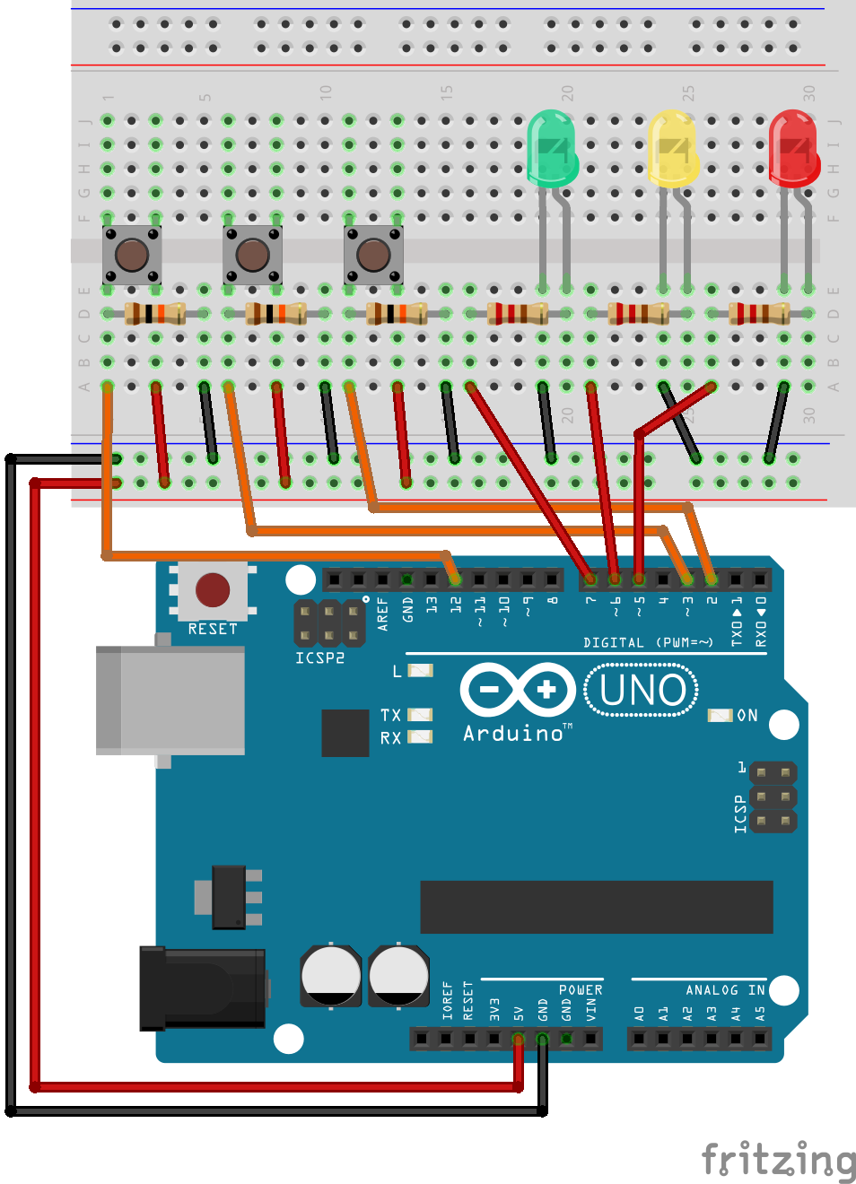
External interrupts are created by sensors (via communication channels) or buttons.
In Arduino an external interrupt handler is defined by the function:
attachInterrupt(digitalPinToInterrupt(pin), ISR, mode)
Practical exercises
Practical exercise: Modify the RGB-LED code such that the blinking should stop immediately as soon as the button is pressed and should continue again as soon as it is released.
Although we are using the delay() function in almost everywhere, it is a very dangerous function. It halts any processing completely. No reading of sensors, mathematical calculations, or pin manipulation can go on during delay function.
Exercise for home: Modify the interrupt code without using delay functions. There is a very nice project using an LCD here:
External interrupt request 0 and 1
The external interrupt requests INT0, and INT1 are triggered by pin 2, and 3 respectively. The following program illustrates how the interrupst may be used to toggle the state of two digital outputs.
#include <Arduino.h>


/*
 * The only pins that support external interrupt on the Arduino UNO is pin 2, and 3.
 */
const uint8_t pushButton1 = 2;
const uint8_t pushButton2 = 3;
const uint8_t pushButton3 = 12;

const uint8_t greenLED = 7;
const uint8_t yellowLED = 6;
const uint8_t redLED = 5;

volatile uint8_t interrupt_2_state_variable = 0;
volatile uint8_t interrupt_3_state_variable = 0;

uint32_t counter = 0;

void external_interrupt_2();
void external_interrupt_3();

void setup() {
  pinMode(pushButton1, INPUT);
  pinMode(pushButton2, INPUT);
  pinMode(pushButton3, INPUT);

  pinMode(greenLED, OUTPUT);
  pinMode(yellowLED, OUTPUT);
  pinMode(redLED, OUTPUT);

  Serial.begin(9600);

  /*
   * attachInterrupt(digitalPinToInterrupt(pin), ISR, mode)
   */
  attachInterrupt(digitalPinToInterrupt(2), external_interrupt_2, RISING);
  attachInterrupt(digitalPinToInterrupt(3), external_interrupt_3, RISING);
}

void loop() {
  //digitalWrite(greenLED, interrupt_2_state_variable);
  //digitalWrite(redLED, interrupt_3_state_variable);

  if(digitalRead(pushButton3)){
    digitalWrite(yellowLED, HIGH);
    sei();
  }
  else{
    digitalWrite(yellowLED, LOW);
    //cli();
  }
  counter++;
  Serial.print("Loop: ");
  Serial.println(counter);
  delay(3000);

}

void external_interrupt_2(){
  interrupt_2_state_variable = !interrupt_2_state_variable;
  digitalWrite(greenLED,!digitalRead(greenLED));
}

void external_interrupt_3(){
  interrupt_3_state_variable = !interrupt_3_state_variable;
  digitalWrite(redLED,!digitalRead(redLED));
}
Pin change interrupts
Note
The pin change interrupts are not supported by the Arduino library, and thus requires manual register manipulation.
The Atmega 328 does not support individual interrupts on all the digital inputs. The pin change interrupts in the Atmega 328 are three interrupt vectors that can be configured to trigger on the change of one or more of a range of input pins. This is often sufficient to make a responsive application, because the ISR can check wich of the input pins that have changed, and thus wich one is responsible for the interrupt. Often the ISR will simply change a flag, or post a message into a queue, and the main process will then take appropirate action when it is ready.
The following code shows a function that configures Arduino pin 11, 12, and 13 for pin change interrupt:
/*
 * Arduino pin 13, 12, and 11 are connected to PCINT 5, 4, and 3.
 */
void interrupt_setup(){

  // Enable pin change interrupts PCINT3, PCINT4, and PCINT5.
  PCMSK0 |= ((1 << PCINT5) | (1 << PCINT4) | (1 << PCINT3));

  // Clear any interrupts on ISR0.
  PCIFR |= (1 << PCIF0);

  // Pin Change Interrrupt Control Register (PCICR)
  PCICR |= (1 << PCIE0);

  sei();
}
The actual code that is executed upon a interrupt is defined as follows:
// Pin change ISR for D8 to D13
ISR (PCINT0_vect){

  // Code to detect which pin is responsible for the interrupt.

}
Pin change interrupt example
The following example shows how to use all three pin change interrupts. Each ISR is responsible for toggling the state of a LED in order to indicate that the program is functional.
#include <Arduino.h>


const uint8_t pushButton1 = 2;
const uint8_t pushButton2 = A1;
const uint8_t pushButton3 = 12;

const uint8_t greenLED = 7;
const uint8_t yellowLED = 6;
const uint8_t redLED = 5;

uint32_t counter = 0;

void pin_change_interrupt_setup();

void setup() {
  pinMode(pushButton1, INPUT);
  pinMode(pushButton2, INPUT);
  pinMode(pushButton3, INPUT);

  pinMode(A0, INPUT);
  pinMode(A1, INPUT);
  pinMode(A2, INPUT);
  pinMode(A3, INPUT);
  pinMode(A4, INPUT);
  pinMode(A5, INPUT);

  pinMode(greenLED, OUTPUT);
  pinMode(yellowLED, OUTPUT);
  pinMode(redLED, OUTPUT);

  pin_change_interrupt_setup();
  Serial.begin(9600);
}

/*
 * Arduino pin 13, 12, and 11 are connected to PCINT 5, 4, and 3.
 */
void pin_change_interrupt_setup(){
  cli();

  // Enable pin change interrupts PCINT3, PCINT4, and PCINT5.
  PCMSK0 |= ((1 << PCINT5) | (1 << PCINT4) | (1 << PCINT3));

  // PCINT8 to PCINT13 are connected to pin A0 to A5.
  PCMSK1 |= ((1 << PCINT8) | (1 << PCINT9) | (1 << PCINT10) | (0 << PCINT11));

  // PCINT16, and PCINT17 are connected to the RX, and TX pin of the UART.
  PCMSK2 |= ((0 << PCINT16) | (0 << PCINT17) | (1 << PCINT18));

  // Clear any interrupts.
  PCIFR |= (1 << PCIF2) | (1 << PCIF1) | (1 << PCIF0);

  // Pin Change Interrrupt Control Register (PCICR)
  PCICR |= (1 << PCIE0);
  PCICR |= (1 << PCIE1);
  PCICR |= (1 << PCIE2);

  sei();
}

void loop() {
  counter++;
  Serial.print(counter);
  Serial.print(" ");
  delay(1000);

}

// Pin change ISR for D8 to D13
ISR (PCINT0_vect){
  digitalWrite(greenLED, !digitalRead(greenLED));
}


// Pin change ISR for A0 - A5
ISR (PCINT1_vect) {
  digitalWrite(yellowLED, !digitalRead(yellowLED));
}

// Pin change ISR for D0 - D7
ISR (PCINT2_vect) {
  digitalWrite(redLED, !digitalRead(redLED));
}
Internal Interrupts
Internal interrupts are interrupts that are triggered by the internal hardware (or software) of the microcontroller. Internal interrupt sources includes timers, various communication hardware such as UART, and software that writes to a interrupt request register.
Timer controlled interrupts
All timers depends on the system clock of your Arduino system. Normally the system clock is 16MHz, but for the Arduino Pro 3,3V it is 8Mhz. So be careful when writing your own timer functions. The timer hardware can be configured with some special timer registers. In the Arduino firmware all timers were configured to a 1kHz frequency and interrupts are gerally enabled.
Timer0 is a 8bit timer. In the Arduino world timer0 is been used for the timer functions, like delay() 484, millis() 1.1k and micros() 497. If you change Timer0 registers, this may influence the Arduino timer function. So you should know what you are doing.
Timer1 is a 16bit timer. In the Arduino world the Servo library 811 uses Timer1 on Arduino Uno (timer5 on Arduino Mega).
Timer2 is a 8bit timer like Timer0. In the Arduino work the tone() 650 function uses Timer2.
Timer3, Timer4, Timer5 are only available on Arduino Mega boards. These timers are all 16bit timers. 3
Note
Since internal timers are created by changing the Timer behaviour through the timer register, we will not cover it here. This subject requires at least intermediate embedded programming skills and datasheet reading. However, this is one of the most important topics in the embedded systems. For those who are willing to learn this topic should know about setup and Use of the Timers* (AVR130: Setup and Use the AVR Timers.
Note
interrupts() and noInterrupts() are used to enable and disable interrupts respectively. They are used for the critical parts of the code. - https://www.arduino.cc/reference/en/language/functions/interrupts/interrupts/. Alternatively the functions sei(), and cli() may also be used.
Timer 1 interrupt example
Note
The following example uses the TimerOne library for controlling Timer 1. Depending on your development environment you may have tomanually install the library.
#include <Arduino.h>
#include <TimerOne.h>

const uint8_t greenLED = 7;
const uint8_t yellowLED = 6;
const uint8_t redLED = 5;

uint32_t counter = 0;

void timer1_interrupt();

void setup() {
  pinMode(greenLED, OUTPUT);
  pinMode(yellowLED, OUTPUT);
  pinMode(redLED, OUTPUT);

  Timer1.initialize(100000);
  Timer1.attachInterrupt(timer1_interrupt);
  Serial.begin(9600);
}

void loop() {
  counter++;
  Serial.print("Iterasjon: ");
  Serial.println(counter);
  delay(1000);
}

void timer1_interrupt(){
  digitalWrite(greenLED,!digitalRead(greenLED));
}
Watchdog timer interrupt
The purpose of the watchdog timer is to reboot the controller if the program should crash. It is a safeguard for poorly designed programs, but even well designed programs may crash if the controller is exposed to external noise (radiation) that messes with the memory.
#include <Arduino.h>
#include <avr/wdt.h>

/*
 * The only pins that support external interrupt on the Arduino UNO is pin 2, and 3.
 */
const uint8_t pushButton1 = 2;
const uint8_t pushButton2 = 3;
const uint8_t pushButton3 = 12;

const uint8_t greenLED = 7;
const uint8_t yellowLED = 6;
const uint8_t redLED = 5;

uint32_t counter = 0;

void watchdog_init();

void setup() {
  wdt_disable();
  pinMode(redLED, OUTPUT);
  Serial.begin(9600);
  Serial.println("Controller started.");

  //wdt_enable(WDTO_2S);

  watchdog_init();
}

void watchdog_init(){
  cli();

  /* MCUSR – MCU Status Register. */
  MCUSR = 0;

  /* WDTCSR – Watchdog Timer Control Register.
   *
   * Watchdog Change Enable must be set to one before updating the prescaler bits.
   *
   * The effect of the various prescaler settings are listed in table 10-3 on
   * page 48 in the datsheet.
   */
  WDTCSR |= (1 << WDCE) | (1 << WDE);// | (0 << WDP3) | (0 << WDP2) | (0 << WDP1) | (0 << WDP0);
  WDTCSR = (1 << WDIE) | (0 << WDE) | (0 << WDP3) | (1 << WDP2) | (0 << WDP1) | (1 << WDP0);
  //WDTCSR |= 0b00011000;
  //WDTCSR =  0b01000000 | 0b100001;

  sei();
}

void loop() {
  counter++;
  Serial.print(counter);
  Serial.print(" ");
  delay(1000);
}

/*
 * Watchdog timer ISR
 */
ISR(WDT_vect) {
  digitalWrite(redLED,!digitalRead(redLED));
}
Practical Exercise: Let’s write a program with an RGB light, blinking each LED for 1 second (reg, green, blue, white) and repeat it infinitely. Also, attach a button that stops blinking of all LEDs. Do not use any interrupt knowledge at first and let’s see what happens. Afterwards, define your button as an interrupt and see what changes.
Detailed look at the operation of the interrupt system
References
- 1
Izmir Institute of Technology - Department of Electrical and Electronics Engineering EE443 - Embedded Systems lecture notes - 2013
- 2
https://www.tutorialspoint.com/embedded_systems/es_timer_counter.htm
- 3
https://www.robotshop.com/community/forum/t/arduino-101-timers-and-interrupts/13072