Serial I/O
In this lesson we will focus on advanced usage of the serial port library in the Arduino. We will not go in to details about how the serial port operate under the hood, the focus will be on how to use the serial port. Still some basic knowledge about the operation is necessary for us to understand the limitations of the interface (and if possible how to overcome the limitations).
Introduction
When communicating with the Arduino UNO we are using a low level protocol known by the acronym UART (or sometimes more generally referred to as USART).
The USB uses a different (and more complex) communication protocol, but drivers on the PC, and a chip on the Arduino board converts this to a simple UART protocol.
The UART operates without a common clock signal for synchronization, hence the asynchronous part of the name. The sender and receiver are synchronized by means of start and stop signals as part of the data stream. For this to work it is important that the sender and receiver both are configured to use the same communication speed, known as the baud rate 1.
We have already used the Serial.begin(9600);, which configured the baud rate to 9600. The baud rate specifies the number of information units (symbols) which are transferred each second. In the UART a symbol is only 1, or 0, thus the baud rate is the same as the bit rate. It is important however to distinguish between the two, as there are many transmission systems which utilize more than two symbols. It is also important to realize that the UART protocol has some overhead (for synchronization purposes it has to transmit more than just the information you want to transfer), thus the actual number of information bits per second will be less than the baud rate setting.
For the example of a baud rate of 9600, a single bit is transmitted in approximately 100 microsecond. The transmission of a complete byte (8 bit) of useful data takes approximately 1 millisecond, since we also have to transmit a start, and stop bit.
Higher level protocol layers
The UART as a communication protocol is very basic and puts few constraints on how information should be transmitted. A higher level application specific communication protocol will often be needed in order to use the UART in a reliable communication system. I.e. any binary data can be transmitted over the UART, but depending on the application only certain sequences of data could be valid. A higher level protocol is thus needed to check if the data is valid.
The serial monitor
The serial monitor typically interpret the binary data it receives as characters, and print them on the display. It will also typically transmit whatever you type on your keyboard to the UART. Characters are typically encoded using ASCII, or unicode. If you are transmitting data which is not valid characters the display on the serial monitor will quickly become confusing and meaningless.
The Arduino Serial library
This section covers the communication between Arduino and a PC using the single hardware UART available on the Arduino Uno.
Warning
It is important to note that the Arduino UNO only has one serial port, which is used for the communication of your software, as well as for uploading new software to your board. Also note that pins 0 and 1 are used for communication with the computer. Connecting anything to these pins can interfere with the serial port communication, including causing failed uploads to the board.
The Arduino functions associated with writing data to the serial port that we will be using in this lesson are:
The Arduino functions associated with reading data from the serial port that we will be using in this lesson are:
Serial output
By serial output in this context we mean data which is transmitted from the Arduino, and received by your PC. We have already been using the serial port for basic printing of data from the Arduino in order to better understand how our program behaves. Now we will explore this in somewhat more detail.
Initialization
Before you can use the Serial object in Arduino it must be initialized with some configuration. Often you will simply see: Serial.begin(9600). This configures the serial port for 9600 bits per second, 8 data bits, one start bit, no parity bit, and one stop bit. This configuration is rather common, and thus it is also the default, when you specify nothing. If you want to be explicit about the start, parity and stop bits, you may use:
Serial.begin(9600,SERIAL_8N1);
Although the bit configuration is often left alone, it is common to adapt the baudrate (remember that in this context the baudrate is the number of bits per second), depending on the requirement of the application. In order to specify the next higher standard baudrate of 19200 (which is \(9600 \cdot 2\)), you may use:
Serial.begin(19200,SERIAL_8N1);
If you wish to use parity, or adjust the number of data bits, there are many predefined configurations. E.g.:
Serial.begin(19200,SERIAL_5E2);
Warning
Unless you understand the implications, and know that you need something else, it is probably best to stay with the default configuration.
The explanation for the seemingly arbitrary baudrate of 9600 (and it’s multiples) lies in the first applications of this kind of communication systems. Old mechanical teletypewriters operated at 75 baud, and thus some of the first modems also used that speed. Later modems used 150 baud, then 300 baud, and then 1200, 2400, and 9600 baud. The goal was to have baudrates which where multiples of 2, as this simplified the design, and allowed one system to easily support multiple baudrates.
Some baudrates that are commonly supported include:
9600
19200
38400
57600
115200
230400
In some cases only some distinct baud rates are supported, while in other cases any arbitrary number can be chosen. For the Atmega328P on the Arduino UNO the baud rate depends on the CPU clock (16 MHz), as well as some settings which divides this clock by a number. You have a lot of freedom in which baud rate to select, but unless you absolutely need to choose something unusual it is best to stick with one of the standard values.
The Serial.write() method
The Serial.write() method writes binary data to the serial port. It is useful for low level writing, when you want the actual number, rather than it’s ASCII representation to be written to the terminal.
E.g. in order to write a lower case “f” to the terminal you may use:
Serial.write(102);
or:
Serial.write("f");
But if you want to write the number 102 (i.e. the integer 102, not the string “102”), such that it is displayed as “102” in the terminal, that number must first be converted to a string. The number is one byte, but it’s ASCII representation is three bytes:
Serial.write(49);
Serial.write(48);
Serial.write(50);
The Serial.write() method stores the data to be transmitted in a buffer, before returning immediately. The actual transmission is handled by a ISR. If the buffer is full however, the method will block until there is sufficient free space. If you cannot afford the risk of the code blocking, you should use the method Serial.availableForWrite() to check if the buffer has free space before writing.
The Serial.print() method
The Serial.print() method simplifies the writing of numbers, as it automatically converts them to ASCII. The following will print the number as ASCII:
Serial.print(102);
The Serial.print() method support a parameter specifying how to print a integer:
Serial.print(154, BIN);prints 10011010.Serial.print(154, OCT);prints 232.Serial.print(154, DEC);prints 154.Serial.print(154, HEX);prints 9A.
If the passed number is floating point, the second parameter is used to specify how many decimal places to use:
Serial.print(1.2345, 2);prints 1.23.
The Serial.println() method
The Serial.println() method works in the same manner as Serial.print() with the addition of a carrige return and line feed appended at the end.
Note
\n: Newline (frequently called line ending, end of line (EOL), next line (NEL) or line break) is a control character or sequence of control characters in a character encoding specification (e.g., ASCII, EBCDIC) that is used to signify the end of a line of text and the start of a new one 2.
In fact, there is no difference between
Serial.print("Hello world");
Serial.print("\n");
and
Serial.println("Hello world");
There are several backslash meaningful characters in C language. Those are called as escape sequences in C. The most used ones in our course are \n for ENTER and \t for TAB.
Serial.print("Hello world\n");
ASCII table (and Unicode)
It is very important to understand how characters are encoded in a computer. As you should know from previous courses, one of the most common coding schemes is known as ASCII (American Standard Code for Information Interchange).

Since ASCII only support the fundamental characters of the english alphabet, another coding scheme known as unicode is used with the goal of supporting all the characters in any language in use by humans (so far it supports more than 130000 characters). Unlike ASCII which uses 7 bit to encode a character, unicode uses various coding schemes. One common scheme known as UTF-8 (8-bit Unicode Transformation Format), encodes the symbols supported by ASCII using 8 bit, while other symbols use 16-bit, 24-bit, or 32-bit, depending on the symbol.
E.g. the UTF-8 encoding for the norwegian character ‘Ø’ (Latin Capital Letter O With Stroke) is the bytes 0xC3 0x98, i.e. a 16 bit encoding.
Example: Serial output of the push button state
Let’s write a program that takes the button state, and writes it on your serial monitor .
This will look like that with your breadboard and Arduino:
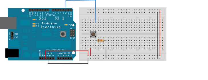
The following code continuously prints the state of the push button to the serial port:
uint8_t button_pin = 2;

void setup() {

  pinMode(button_pin, INPUT);

  Serial.begin(9600);
}

void loop() {
  uint8_t button_state = digitalRead(button_pin);
  Serial.println(button_state);
  delay(1);
}
Serial input
When the Arduino receives data on the serial port the data is automatically stored in a buffer. When the buffer is full, Arduino ignores any new data until the buffer is drained. Several of the functions used to access this buffer, automatically frees the memory.
The Serial.read() method
In order to read a single byte from the serial port we may use the Serial.read() method.
Serial.read();
It is pointless to read the serial port if no data is available, thus we use the Serial.available() method to check if there is data in the buffer first.
Serial.available();
The Serial.read() method returns “-1” if no data is available on the serial port. This could have been used to check if the buffer is empty, but it can also be problematic if one wishes to use it for a binary communication protocol, where the binary code for “-1” could be part of the transmission. Thus it is better to use the Serial.available() method.
The following example shows how to read all keystrokes in the terminal, and feed back the ASCII code, as well as the character:
void setup() {
  Serial.begin(9600);
  Serial.println("Press any key: ");
}

void loop() {

    uint8_t data;

    if(Serial.available()){
        data = Serial.read();
        Serial.print("Data: ");
        Serial.print(data);
        Serial.print(" : Tegn: ");
        Serial.write(data);
        Serial.print("\n");
    }
}
Arrays
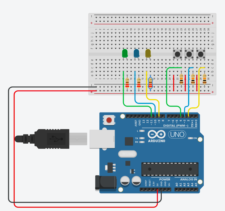
An array (Norwegian: “oppstilling”, or “tabell”) is a data structure consisting of a number of elements (values) identifiable by a index number. It is one of the most important subject in all programming languages. It allows you to store linked variables in an ordered way in the memory. In this manner, arrays are the most fundamental type of data structures. The way how the variables are stored in the memory allows us to iterate through those linked elements.
In a basic way which we have been using so far, we define one variable name for each variable. And then, we manipulate that variable by calling it in the program. Let’s look at the following examples. You will see 3 buttons and 3 individual LED states in the circuit. In the code, only 2 buttons control 2 LEDs, individually.
const int inputPin1 = 2;
const int inputPin2 = 3;

const int ledPin1 = 9;
const int ledPin2 = 10;

void setup(){
  Serial.begin(9600);

  pinMode(inputPin1, INPUT); // optional
  pinMode(inputPin2, INPUT); // optional

  pinMode(ledPin1, OUTPUT);
  pinMode(ledPin2, OUTPUT);
}

void loop(){
  bool val1 = digitalRead(inputPin1);
  if (val1 == LOW){
      digitalWrite(ledPin1, HIGH);
    }
    else{
      digitalWrite(ledPin1, LOW);
    }

  bool val2 = digitalRead(inputPin2);
  if (val2 == LOW){
      digitalWrite(ledPin2, HIGH);
    }
    else{
      digitalWrite(ledPin2, LOW);
    }
}
The program above is already unnecessarily long with only 2 buttons and 2 LEDs. I cannot implement a loop easily because the variable names are not nicely connected. In other words, they are not defined in an iterable way. The code can be rewritten as such:
const int inputPins[3] = {2,3,4};
const int ledPins[3] = {9,10,11};
void setup(){
  for(int i = 0; i < 3; i++){
    pinMode(ledPins[i], OUTPUT);
    delay(1);
    pinMode(inputPins[i], INPUT);
    delay(1);
  }
  Serial.begin(9600);
}
void loop(){
  // optimize this this part later in exercises.
  // Note that index number starts from zero.

  Serial.print(digitalRead(inputPins[0]);
  Serial.print(digitalRead(inputPins[1]);
  Serial.println(digitalRead(inputPins[2]);
}
The Serial.readBytes() method
The Serial.readBytes() method reads one or more bytes from the serial port, and stores them in a specified buffer. The method is blocking until the specified number of bytes are received, or a timeout occurs. The timeout delay is configured by the method Serial.setTimeout().
Serial.readBytes(buffer, length)
The binary nature of this function makes it usefull for binary transfers, but more complicated to use for normal text.
The following example reads a maximum of five bytes from the serial port. If five bytes are received, or a timeout occurs, the data is printed back on the serial port.
#include <Arduino.h>

const uint8_t max_rx_size = 5;

uint8_t rx_data[max_rx_size];

void setup() {
  Serial.begin(9600);

  // Set the timeout to 5 seconds.
  Serial.setTimeout(5000);
}

void loop() {
  Serial.print("Type your message: ");

  Serial.readBytes(rx_data, 5);

  Serial.write(rx_data[0]);
  Serial.write(rx_data[1]);
  Serial.write(rx_data[2]);
  Serial.write(rx_data[3]);
  Serial.write(rx_data[4]);

  Serial.print("\n");
}
The Serial.readString() method
The Serial.readString() method reads one or more bytes from the serial port, and stores them i a specified buffer. The method takes no parameters, and returns on a timeout.
Serial.readString()
The following example reads data from the serial port until a timeout occurs.
#include <Arduino.h>

void setup() {
  Serial.begin(9600);

  // Set the timeout to 5 seconds.
  Serial.setTimeout(5000);
}

void loop() {
  Serial.print("Type your message: ");
  String message = Serial.readString();

  Serial.print("\n");
  Serial.print("You typed: ");
  Serial.println(message);
}
The Serial.readStringUntil() method
The Serial.readStringUntil() method reads data from the serial port until it reaches a termination character.
Serial.readStringUntil(terminator)
The following example reads data from the serial port until a newline character is received (i.e. you press ENTER), or a timeout occurs. The data is then written back to the serial port.
#include <Arduino.h>

void setup() {
  Serial.begin(9600);

  // Set the timeout to 5 seconds.
  Serial.setTimeout(5000);
}

void loop() {
  Serial.print("Type your message: ");
  String message = Serial.readStringUntil('\n');

  Serial.print("\n");
  Serial.print("You typed: ");
  Serial.println(message);
}
Switch-case
The switch case structure is an alternative to if, and else if which can provide better structure when we have a large number of choices. In terms of serial communication it can be used to take different actions depending on what you receive on the serial port.
One example could be the improvement of one of the early if…else exercises: Exercise: Serial UI for LED control. The solution of this example would be something like that:
//LED on off through Serial

const int led_pin = 8;

char rx_byte;

void setup(){
  Serial.begin(9600);
}

void loop(){
  if(Serial.available() > 0)
  {
    rx_byte = Serial.read();

    if(rx_byte == '1'){
      Serial.println("LED is ON");
      digitalWrite(led_pin, HIGH);
    }

    else if(rx_byte == '2'){
      Serial.println("LED is OFF");
      digitalWrite(led_pin, LOW);
    }

    else if(rx_byte == '3'){
      Serial.println("HELP MENU");
      Serial.println("----------");
      Serial.println("1. LED ON");
      Serial.println("2. LED OFF");
      Serial.println("3. HELP MENU");
      Serial.println("----------");
    }


    else{
      Serial.println("Invalid Operation");
      Serial.println("----------");
      Serial.println("1. LED ON");
      Serial.println("2. LED OFF");
      Serial.println("3. HELP MENU");
      Serial.println("----------");
    }
  }
}
This code could have been written using another syntax, which is Switch-case.
const int led_pin = 8;

char rx_byte;

void setup(){
  Serial.begin(9600);
}

void loop(){
  if(Serial.available() > 0)
  {
    rx_byte = Serial.read();

    switch (rx_byte)
    {
    case '1':
      Serial.println("LED is ON");
      digitalWrite(led_pin, HIGH);
      break;

    case '2':
      Serial.println("LED is OFF");
      digitalWrite(led_pin, LOW);
      break;

    case '3':
      Serial.println("HELP MENU");
      Serial.println("----------");
      Serial.println("1. LED ON");
      Serial.println("2. LED OFF");
      Serial.println("3. HELP MENU");
      Serial.println("----------");
      break;

    default:
      Serial.println("Invalid Operation");
      Serial.println("----------");
      Serial.println("1. LED ON");
      Serial.println("2. LED OFF");
      Serial.println("3. HELP MENU");
      Serial.println("----------");
      break;
    }
  }
}
The following code listing provides an example of a fancy usage of the Switch-case structure to set the color of a serial terminal. The actual code involved in setting the color (that strange stuff inside the calls to Serial.print()) is outside the curriculum. Still this example hopefully serve as a good demonstration that such switch case structures can be useful.
typedef enum {
  BLACK = 0,
  RED,
  GREEN,
  YELLOW,
  BLUE,
  MAGENTA,
  CYAN,
  WHITE,
  RESET
} color_t;

void set_terminal_color(color_t color){

  switch (color)
  {
  case BLACK:
    Serial.print("\x1b[30m");
    break;
  case RED:
    Serial.print("\x1b[31m");
    break;
  case GREEN:
    Serial.print("\x1b[32m");
    break;
  case YELLOW:
    Serial.print("\x1b[33m");
    break;
  case BLUE:
    Serial.print("\x1b[34m");
    break;
  case MAGENTA:
    Serial.print("\x1b[35m");
    break;
  case CYAN:
    Serial.print("\x1b[36m");
    break;
  case WHITE:
      Serial.print("\x1b[37m");
    break;
  case RESET:
    Serial.print("\x1b[0m");
    break;
  default:
    Serial.print("\x1b[0m");
    break;
  }
}
Exercises
Exercise: Servo motor control
The following code listing shows how to
#include <Servo.h>
int serialVal;

Servo myServo;

void setup() {
  Serial.begin(9600);
  myServo.attach(9);
}

void loop() {
  if(Serial.available() > 0)
  {
    serialVal = Serial.read() - 48;
    serialVal = map(serialVal, 0, 5, 0, 180);
    Serial.println(serialVal);
    myServo.write(serialVal);
  }
  delay(10);
}
Make a sketch of how you are going to wire the servo motor to the Arduino UNO.
Copy the code listing, and upload it to your board.
Open a serial monitor, and test the program.
Write a few paragraphs which describe the operation of the program in detail. Include what are the valid input parameters, what is the resolution in the motor control, and why to we subtract 48.
Exercise: Triple button, triple LED
Complete the exercise such that 3 individual buttons control 3 individual LEDs using for loop and arrays.
const int inputPins[3] = {2,3,4};
const int ledPins[3] = {9,10,11};
void setup(){
  for(int i = 0; i < 3; i++){
    pinMode(ledPins[i], OUTPUT);
    delay(1);
    pinMode(inputPins[i], INPUT);
    delay(1);
  }
  Serial.begin(9600);
}
void loop(){
  // fill this part
}
Exercise: Annoying a and b
Can you swap these two variables?
void setup()
{
  Serial.begin(9600);
}

void loop()
{
  int a = 5;
  int b = 7;

  Serial.print("Before:\t");
  Serial.print(a);
  Serial.print("\t");
  Serial.println(b);

  my_swap_func(a, b);
  delay(1000);

}

void my_swap_func(int a, int b){

  /*SWAP HERE*/

  Serial.print("After:\t");
  Serial.print(a);
  Serial.print("\t");
  Serial.println(b);

}
Note
Always be careful about the scope of a function. Note that it is not possible to change a and b inside the swap function and print it outside, in the loop function. Even though, you define a and b as global variables as long as you are passing them as an argument to the swap function, they will be behaved as local variable.
However, within our current knowledge, arrays can do that. Check out the following code. There is no Serial.print() in our swap function. The explanation of this possibility relies on pointers. When you pass an array as an argument, you actually pass the address of the first element.
To have an influence on a passed argument (an input of a function), you need to deal with its pointer, which is not the scope of this course.
void setup()
{
  Serial.begin(9600);
}

void loop()
{

  int my_arr[2] = {5, 7};
  Serial.print("Before:\t");
  Serial.print(my_arr[0]);
  Serial.print("\t");
  Serial.println(my_arr[1]);

  my_swap_func(my_arr);

  Serial.print("After:\t");
  Serial.print(my_arr[0]);
  Serial.print("\t");
  Serial.println(my_arr[1]);

  delay(1000);

}

void my_swap_func(int arr[]){
  /*THE SAME SWAP ALGORITHM*/
}
Footnotes