Analog to digital conversion (ADC)
In the previous lesson we discussed digital to analog conversion. In this lesson we consider the opposite process, where a analog signal is converted in to a digital representation.
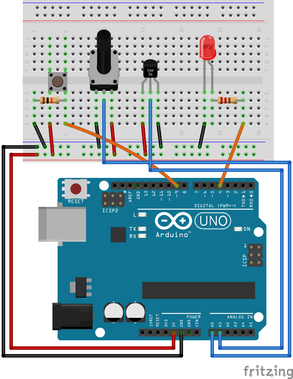
In order to be prepared for most of the exercises in this lesson, the following connections should be made in advance:
Introduction
Analog to digital converters (ADC) and digital to analog converters (DAC) are the bridges between digital and analog worlds.
The analog to digital converter has many applications, some of which include:
Reading of potentiometer settings
Reading of temperature sensors, pressure sensors, light sensors, strain sensors, etc.
Reading the voltage on a battery in order to determine the state of charge (sometimes combined with a temperature reading, since battery voltage can be affected by temperature)
Measurement of EMF in order to determine the rotational speed of a motor
Measurement of voltage and current in power systems in order to calculate active (P), and reactive (Q) power.
Reception of radio signals for use in a software defined radio (SDR)
Analog to digital converter
An A/D converter (analog to digital converter) is a device that converts a analog signal into an approximate digital representation. It measures the ratio of an analog input value to a reference value and express it in a form of digital value. Many different technologies exits for this purpose, where each one has it’s own advantages and disadvantages. The following is a list of the more common types:
Successive Approximation (SAR) ADC.
Delta-sigma (ΔΣ) ADC.
Dual Slope ADC.
Pipelined ADC.
Flash ADC
The Atmega328p of the Arduino UNO has a successive approximation ADC, and the operation of this type of converter will be discussed briefly. The other types will not be discussed further in this lecture.
Successive Approximation (SAR) ADC.
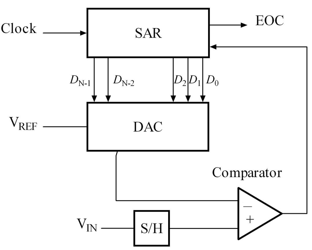
The successive approximation ADC uses a binary search method to go through all possible quantization levels for the digital representation for the analog value, until it finally reaches the best approximation.
The analog value is sampled, and a constant voltage sample is held in the sample and hold (S/H) circuit. This voltage sample is then compared to the output voltage from a digital to analog converter (DAC), which initially is set to zero volts. The comparator then informs the successive approximation register whether the sampled voltage is above or below the DAC output. If the sampled voltage is higher than the DAC output, the successive approximation register increase the DAC output on the next clock cycle. This process continues on each clock cycle until the DAC output becomes higher than the sampled value.
The digital signal which is required to control the DAC in such a way that it outputs a voltage approximately equal to the sampled voltage, is then used as the digital representation of this analog voltage. The end of conversion (EOC) signal informs the processor that the conversion process is completed.
It should be obvious from the above explanation that the analog to digital converter needs some time to complete the conversion process. The time it takes to complete one conversion is one of the fundamental parameters describing an ADC.
Quantization
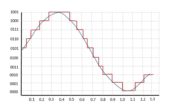
Quantization is the main step in digitizing an analog signal. Basically, categorize an analog signal into subset of digital values which can be expressed in desired resolution. Let’s have a look at a quantized sinusoidal signal in 4-bits resolution.
Sampling depth is the minimum smallest analog value change that is detectable.
Sampling rate is the number of samples taken for quantization.
Note that as we discussed before that we cannot every possible analog output in digital world (as we encounter conversion error), we cannot measure every possible analog input with an infinite precision, either.
See also
Considering the fact that your reference analog voltage is 5V and you are using 10-bit ADC converter in Atmega328p, what is the minimum analog voltage difference you can distinguish?
See also
Do you think if there is any limitation of how fast/slow you can sample a signal? What is the advantages and disadvantages of sampling fast/slow?
Important parameters for ADC operation
There are many important parameters one should understand when applying an A/D converter. Even if a particular ADC is selected, there are still many parameters that can be adjusted within the ADC depending on how you intend to use it. The following is a summary of a few basic ones:
Resolution - The digital representation of the analog signal must use a finite number of bits, and this imposes limitations on the smallest possible change in the analog value that is detectable by the converter.
Sampling frequency - The conversion from analog to digital takes up a finite time, and this imposes limitation on how fast changes in the analog signals that are detectable.
Aliasing - If the measured analog signal contains components with a frequency that is higher than half of the sampling frequency, there is a risk of aliasing. The risk is that the resulting digital representation contains frequency components that does not exist in the real analog signal.
Dymaic range - The range of signal amplitudes that the ADC can resolve.
For simple applications with values that vary slowly (e.g. temperature measurements), it might be sufficient to only take these parameters into account. For more demanding applications (e.g. real time current measurements in a motor drive), one should obtain a deeper knowledge of all the parameters that will impact the performance.
The analog input or output range is determined by a reference voltage, \(V_{ref}\). Typically for an N-bit converter with unsigned digital I/O and unipolar analog range \((0V .. +V_{ref})\), one step at the analog end, \(\Delta V_{LSB}\), is given by:
Similarly for a bipolar analog range \((-V_{ref} .. +V_{ref})\), one step at the analog end is:
Another important thing is that the ADC is super slow process in 16 Mhz (about 62 ns) levels. For comparison, digitalRead() takes 4.9us whereas analogRead() 104us! For now, we keep the ADC in our main process but there are other ways to optimize your program when you need to include such a bulky process in your applications.
Using the ADC in Arduino
The Arduino UNO has six analog inputs on the pins A0 to A5. There is only a single ADC, but some internal switches allows us to select which of the inputs is sampled. By default the voltage range on each input is 0 - 5 V.
In the Arduino library the function analogRead() can be used to read data from the ADC. E.g. analogRead(A0) in order to read the first analog input. This is a blocking function, meaning the program will stop and wait for the conversion process to complete before the function returns. The ADC has a resolution of 10 bit, which means that the value returned from analogRead() will be a number between 0, and 1023. There is no 10 bit datatype, and in the function declaration the return type is set to int, which is a 16 bit signed number on the Arduino UNO. In reality it can never be negative, and thus a unsigned int, or uint16_t could have been used.
The ADC will convert the analog input voltage (0 - 5 V) in to a number (0 - 1023). If you are interested in knowing the voltage level, some basic calculations has to be performed after the conversion is completed.
If the number returned from analogRead() is 400, the voltage is given by:
You should also consider how many significant figures you can have in this number. I.e. how many volts do you have per bit.
The conversion time is approximately 100 microseconds, which means that it is possible to perform 10000 conversions each second. This is not the absolute maximum speed of the ADC, it is simply how the ADC is configured inside the Arduino library.
Exercise: print raw ADC value to serial port
In this exercise you will experience how various voltages applied to analog input A0 affects the value returned from analogRead().
Write a simple program that is able to print a message to the serial port at a given interval. Use
millis()to obtain the delay, and use a interval of 2 seconds.Extend the program so that the value printed to the serial port is the raw value returned from
analogRead().Test the program by applying various voltages to the A0 port. Try 5 V, 3.3 V, GND, and optionally a resistive voltage divider using two resistors.
Example: Temperature measurement using TMP36
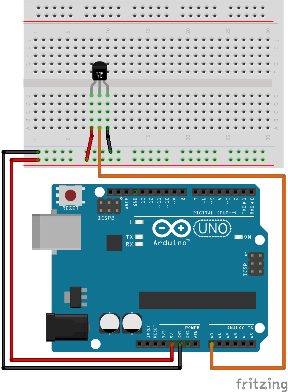
In this example we will be reading the temperature from the TMP36 sensor that is included in the Arduino kit. The TMP36 has a voltage output linearly proportional to the temperature, and thus makes it easy to measure temperatures without any curve fitting that must be used with nonlinear sensing elements.
The details of how the TMP36 operates are available in the datasheet
Connect the sensor according to the following diagram:
The following source code listing shows how to read the sensor, and how to convert the raw reading to voltage, and temperature:
Note
Try to change the program to use millis() instead of delay().
#include <Arduino.h>

void setup() {
        Serial.begin(9600);
}

void loop() {
        int sensorVal = analogRead(A0);
        float sensorVolt = (sensorVal/1024.0)*5;
        float temperature = (sensorVolt - 0.5)*100;

        Serial.print("Sensor verdi: ");
        Serial.print(sensorVal);
        Serial.print("\n");

        Serial.print("Sensor spenning: ");
        Serial.print(sensorVolt);
        Serial.print("\n");

        Serial.print("Sensor temperatur: ");
        Serial.print(temperature);
        Serial.print("\n");
        delay(2000);

}
Exercise: Change the unit of temperature measurement
Use the program in the previous example as basis, and add the code required to print the temperature in Kelvin to the serial port.
Extend the program by printing the temperature in Fahrenheit, and Rankine.
Example: Potentiometer as Analog Input
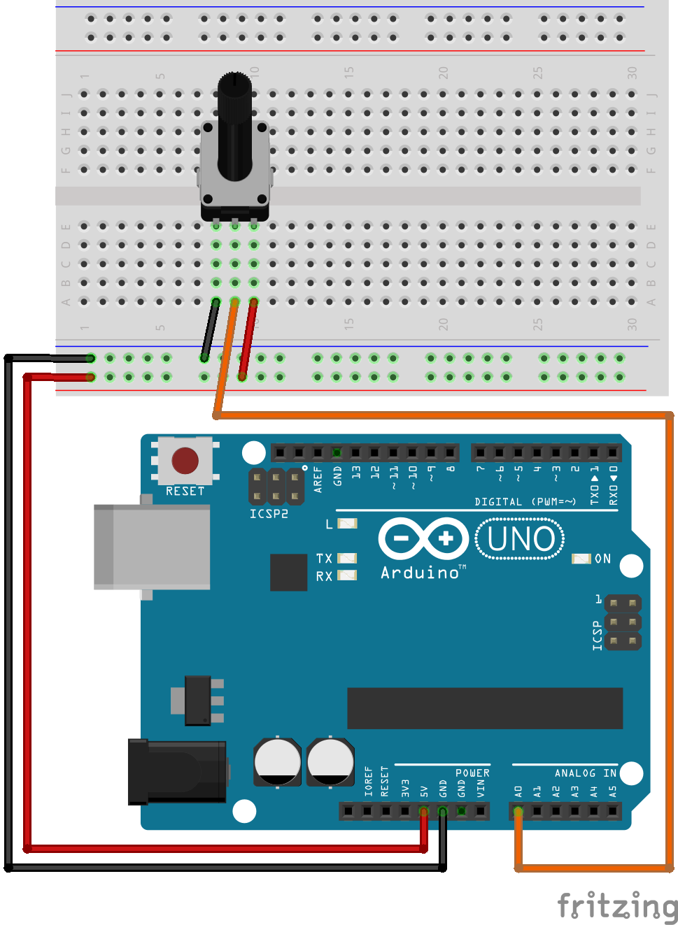
A potentiometer is a type of variable resistor with 3 connections. Two of the connections are placed at the extreme ends of the resistor, for ease of discussion we will name them connector (1), and (2). I.e. the resistance between pins (1), and (2) is always equal to the maximum resistance of the variable resistor. The third connector (3) is connected to a sliding contact, which moves along the resistor. At one extreme end this sliding connector is at (or close to) connector (1), at the other extreme it is at connector (2).
By applying a fixed voltage between connector (1), and (2), the voltage at the sliding contact (3) will vary linearly with the rotation of the potentiometer knob.
You can use this potentiometer value for various different purposes. Now, assume that your microcontroller team is assigned to develop a simple heat display system. If the temperature is higher than 30 celcius, the display gives a warning. If it is between 20-30 celcius, everything is fine. If it is less than 20 celcius, then your display system warns again. To have a temperature sensor (in real life) and physically change the temperature of the room for the sake of test is not very efficient. We all know that temperature sensor gives an analog signal so I can test the system using a potentiometer to emulate the sensor.
For this example you should use the following circuit:
void setup() {
        Serial.begin(9600);
}

void loop() {

        int sensorVal = analogRead(A0);
        float sensorVolt = (sensorVal/1024.0)*5;
        float temperature = (sensorVolt - 0.5)*100;

        Serial.print("Raw value: ");
        Serial.print(sensorVal);
        Serial.print("\t");

        Serial.print("Voltage: ");
        Serial.print(sensorVolt);
        Serial.print("\t");

        Serial.print("Temperature: ");
        Serial.print(temperature);
        Serial.print("\n");

        if(temperature >=30)
                Serial.print("Warm");

        else if((temperature >=20)&&(temperature <30))
                Serial.print(":)");

        else
                Serial.print("Cold");

        delay(1000);

}
Note
After you have finished testing the software using a potentiometer to emulate the temperature sensor, you should connect a real temperature sensor for the final test. There is always a risk that there is something you did not take in to account when performing the emulated test.
Exercise: Potentiometer adjustable blink rate
In this exercise you will develop a program which allows adjusting the blink rate (frequency) of a LED by means of a potentiometer.
Write a program which blinks a LED using
millis()for the delay.Connect a potentiometer to input A0, and add the code required to sample the potentiometer value at a rate of 10 milliseconds.
Use the potentiometer value to control the blink frequency of the LED. The minimum setting should be 0.5 Hz, and maximum should be 25 Hz.
Exercise: Temperature alarm (challenging)
In this exercise you will expand the temperature reading example in to a program that generates a alarm signal if the temperature exceeds a level of 27 degrees. The temperature alarm limit is set to this value so that it will be easy to test, it is above the typical room temperature, but below the body temperature (or the temperature of your coffee).
Start by connecting the TMP36, as well as a push button, and a red LED to the Arduino.
Write a program which continuously reads the temperature value, and compares it to a alarm limit defined by a constant variable. Use
millis()instead ofdelay()for delaying the execution time for the sampling. Use a interval of 1 second. For easy debugging the actual temperature value should be printed to the serial terminal at each sampling interval.Extend the program with the code required to initiate blinking of the LED, and printing of the text “Temperature alarm!” to the serial port as soon as the temperature exceeds the limit. The alarm should not stop, even if the temperature goes back down again below the alarm limit.
Add an alarm acknowledge push button function. If the button is pushed, and the temperature is below the alarm limit, the LED blink, and alarm message should go away. For this functionality debouncing is not needed, as acknowledging an already acknowledged alarm will not perform any action.
Servo motor control
Servo motors is a category of motors designed specifically for accurate control of angular (or sometimes linear) position. There are many different variations of these motors, which require different types of driving circuits. Sometimes the driving can be challenging, but luckily Arduino kit includes a nearly plug-and-play solution.
Example: Servo and map function
The servo motor in the Arduino kit is of the pulse width controlled type. That is, the control signal is a PWM signal, the actual motor control system is an electronic circuit placed inside the motor housing. The PWM is simply used as a way to inform the motor controller of what angular position you would like the motor to have. There is an internal position sensor inside the motor, which measures the shaft position, and a controller which compares this measured value to the commanded value.
The PWM control signal switching frequency should be 50 Hz, and the pulse width (duty-cycle) determine the set point for angular position. A pulse width of 1 ms correspond to 0 degree, 1.5 ms correspond to 90 degree, while 2 ms correspond to 180 degree. This is not standardized however, and motors from other manufacturers might have different interpretation of the pulse widths.

Note that there are a lot of details behind the operation of this motor, some of which will be covered in a future lecture. For now we will simply explore how to use the motor.
The purpose of this example is to control the position of the motor using a potentiometer. In order to simplify the process of generating the required motor pulses, we will be using a library which provides a function to set the correct PWM output for a given numeric value corresponding to a desired angular position.
The library is included by #include <Servo.h>
Warning
The servo motor in the Arduino kit is quite fragile. If you try to rotate with hand or hold it while it is trying to rotate, then you may damage the gear box in it. Please don’t!
First of all, let’s build the following circuit. Notice that there is a capacitor connected between 5 V, and ground. The purpose is to stabilize the voltage in case the servo motor pulls large transient currents. Make sure you connect this capacitor with correct polarity.
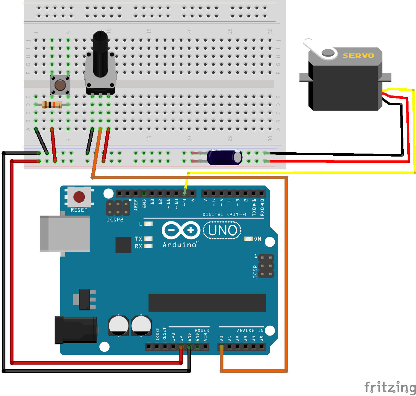
The servo motor has three wires: power, ground, and signal. The power wire is typically red, and should be connected to the 5V pin on the Arduino or Genuino board. The ground wire is typically black or brown and should be connected to a ground pin on the board. The signal pin is typically yellow or orange and should be connected to one of the pins which support PWM. Here we use pin 9.
The potentiometer should be wired so that its two outer pins are connected to power (+5V) and ground, and its middle pin is connected to analog input A0 on the board.
 #include <Servo.h>  // add servo library

 Servo myservo;  // create servo object to control a servo

 const int potPin = A0;  // analog pin used to connect the potentiometer
 int val;    // variable to read the value from the analog pin

 void setup() {
     myservo.attach(9);  // attaches the servo on pin 9 to the servo object
 }

 void loop() {
     val = analogRead(potPin);            // reads the value of the potentiometer (value between 0 and 1023)
     val = map(val, 0, 1023, 0, 180);     // scale it to use it with the servo (value between 0 and 180)
     myservo.write(val);                  // sets the servo position according to the scaled value
     delay(15);                           // waits for the servo to get there
 }
The map function is discussed in the previous lesson, it involves relatively simple calculations and could easily be performed by:
val = (val*180)/1023;
Note that the above calculation require that the intermediate calculations are 32 bit, since 1023*180 yields a number to large to be stored in 16 bits. Thus val has to be declared uint32_t, or some other mechanism must be employed to ensure that the intermediate result is stored using 32 bits of memory. The map() function takes care of this by performing all calculations using 32 bit.
Exercise: Control the servo position based on light on phototransistor
In this exercise we will use the ADC to digitize the voltage from a phototransistor of the type HW5P-1, and use the value returned from the ADC to control the position of a servo motor.
The HW5P-1 phototransistor has two connections, collector and emitter. The base is the light sensitive element of the component, and thus no electrical base connection is available. The long lead is the emitter, and the short one is the collector. In order to use the transistor for light intensity measurements, it should be connected in series with a resistor of 1 - 2 kOhm in the collector, or emitter.
Exercise: Toggle position setting by pushing a button
This exercise builds upon the example from the previous section.
Add the required code to detect the rising edge of a push button, including debouncing. Write a message to the serial port each time a debounced rising edge is detected.
Use the rising edge to toggle the position of the servo motor in steps of 45 degrees. As soon as you reach 180 degree, the direction should change, i.e. you should step backwards from 180 towards zero with steps of 45 degree.
Exercise: Check the potmeter value before commanding the servo motor
The following code example will light up a LED if the commanded value is above 90 degree. In this exercise the example should be expanded with some code which only initiate the movement if the user presses a push button.
 #include <Servo.h>  // add servo library

 Servo myservo;  // create servo object to control a servo

 const int potPin = A0;  // analog pin used to connect the potentiometer
 const int ledPin = 12; // output pin for the LED

 int val;    // variable to read the value from the analog pin

 void setup() {
     myservo.attach(9);  // attaches the servo on pin 9 to the servo object
 }

 void loop() {
     val = analogRead(potPin);            // reads the value of the potentiometer (value between 0 and 1023)
     val = map(val, 0, 1023, 0, 180);     // scale it to use it with the servo (value between 0 and 180)

     myservo.write(val);                  // sets the servo position according to the scaled value

     if(val > 90){
         digitalWrite(ledPin, HIGH);
     }
     else{
         digitalWrite(ledPin, LOW);
     }
     delay(15);                           // waits for the servo to get there
 }
Make sure that the above code is operating as expected on you Arduino. The servo motor should follow you commands, and the LED should light up if the command is above 90 degree.
Add code to continuously print the commanded servo angle to the serial port. Use
millis()to limit the printing to only once a second.Add, and test the code which is required to detect the rising edge of a push button.
Protect the
myservo.write()method so that it is only called if the button is pushed.